Method and apparatus for forming resin film

a resin film and resin technology, applied in the direction of filament/thread forming, turning machine accessories, drawing profiling tools, etc., can solve the problems of resins being likely to separate from each other, the boundary between them is likely to be in disorder, and the resin yield may be reduced

Inactive Publication Date: 2004-06-10
FUJIFILM CORP
View PDF19 Cites 10 Cited by
  • Summary
  • Abstract
  • Description
  • Claims
  • Application Information

AI Technical Summary

Problems solved by technology

When the resin film is formed of a resin hard to recycle or poor in thermal stability, the trimmed-off selvages cannot be recycled, which leads to decrease in the yield of the resin film.
However, the techniques still have disadvantages in that when the physical properties of the resins for the middle portion and for the edge portions of a resin film are different or the film forming condition such as applying condition is different, the resins are likely to separate from each other or the boundary between them is likely to be in disorder.
If the boundary is in disorder, the proportion of the inclusion of the resin for the middle portion to the trimmed-off selvages becomes large, which causes not only the deterioration of the resin film recyclability, but also the decrease in productivity, due to the decrease in the portion as a resin film main body.
However, this has the disadvantage in that, since the resin for the edge portions is wrapped up in the resin for the middle portion, the resin for the middle portion accounts for a larger part of the resin of the trimmed-off selvages than the resin for the edge portions, causing the deterioration in not only recyclability but also productivity.
However, even with these apparatuses, the problems of the film separation of the resins and the disorder at the boundary between the resins cannot be resolved.
Generally, the larger the difference in extrusion rate between the resin for the middle and the resin for the edge portions becomes, the more the disorder is likely to occur at the boundary between the resins.

Method used

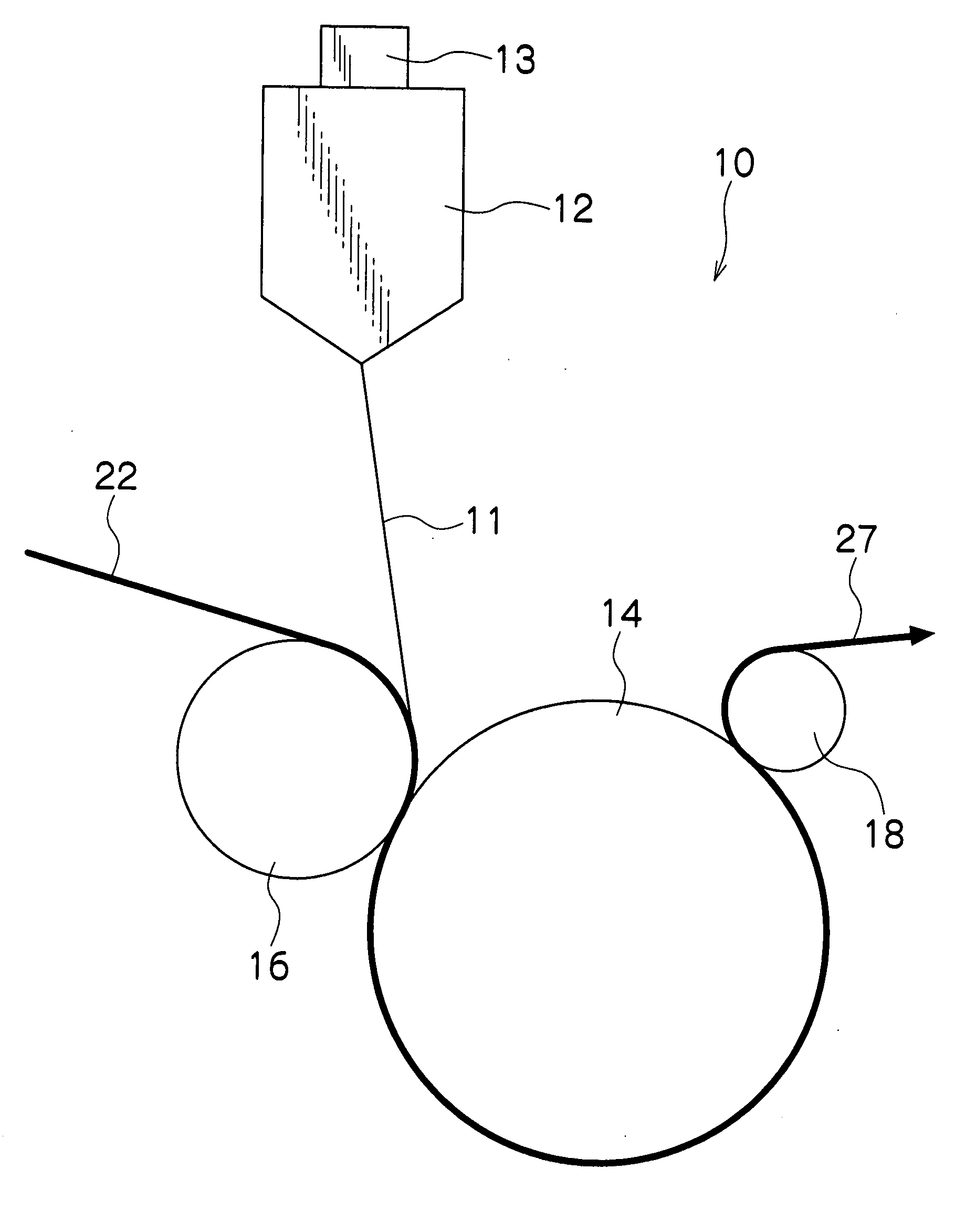
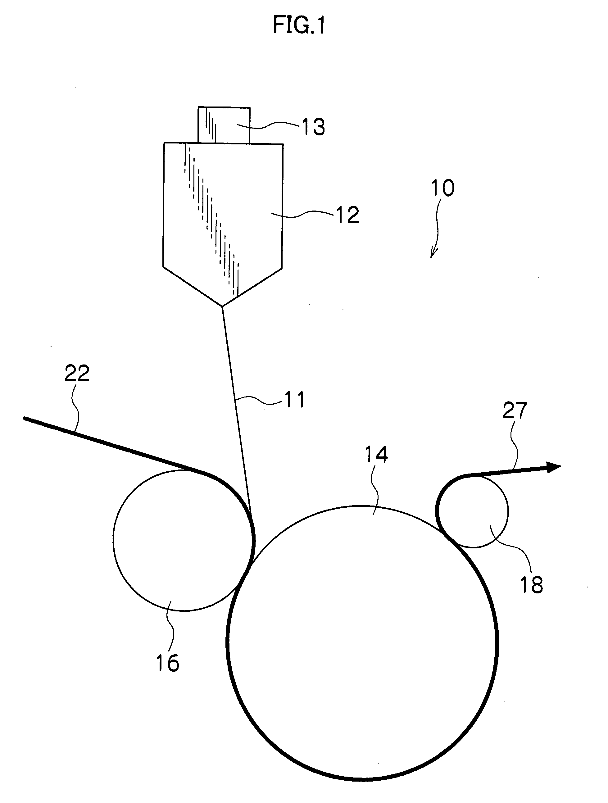

Image

  • Method and apparatus for forming resin film
  • Method and apparatus for forming resin film
  • Method and apparatus for forming resin film

Examples


example 1

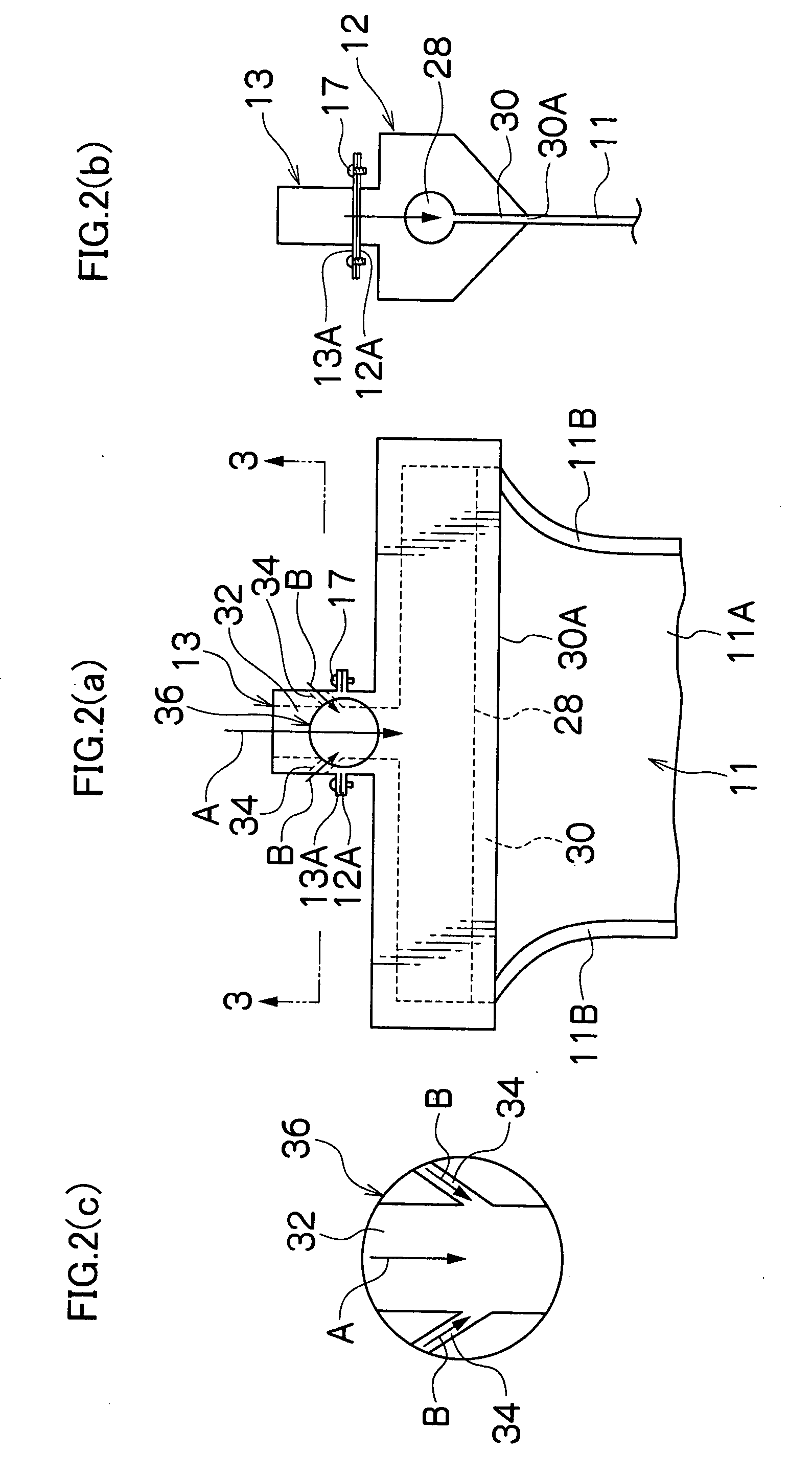
[0051] The same resin A for the middle portion, the same resin B for the edge portion, along with the same extruding die of 1 meter in width as those of Comparative Example 1 were used. A feed block 13 used was such that its joining part 36 was to form a lamination resin 15 by the joining method according to an embodiment of the present invention in which the resin A for the middle portion and the resin B for the edge portions were joined together in such a manner as to enclose the side edge portions of the resin film main body 11A, which was formed of the resin A for the middle portion, in the resin B for the edge portion, as shown in FIG. 7.

example 2

[0053] The same resin A for the middle portion, the same resin B for the edge portion, along with the same extruding die 12 of 1 meter in width as those of Comparative Example 2 were used. The resin A for the middle portion and the resin B for the edge portions were joined and layered in a feed block 13 and extruded through the extruding die 12 to form a resin film 11. The feed block 13 used was such that its joining part 36 was to form a lamination resin 15 as shown in FIG. 7 by the joining method according to an embodiment of the present invention.

example 3

[0055] The same resins A.sub.1 and A.sub.2 for the middle portion, the same resin B for the edge portion, along with the same extruding die 12 of 1 meter in width as those of Comparative Example 3 were used. The resins A.sub.1 and A.sub.2 for the middle portion and the resin B for the edge portions were joined and layered in a feed block 13 and extruded through the extruding die 12 to form a resin film 11. The feed block 13 used was such that its joining part 36 was to form a lamination resin 15 as shown in FIG. 9 by the joining method according to an embodiment of the present invention.


PUM

PropertyMeasurementUnit
weightaaaaaaaaaa
diameteraaaaaaaaaa
diameteraaaaaaaaaa

Abstract

The apparatus is for forming a resin film from a resin for a middle portion to form a resin film main body of the resin film and a resin for edge portions to form both side edge portions in a crosswise direction of the resin film. The apparatus comprises: a feed block which includes a joining part where the resin for the middle portion in a molten state and the resin for the edge portions in a molten state are joined in such a manner as to enclose both side edges in the crosswise direction of the resin film main body with the resin for the edge portions; and an extruding die through which the joined resins are extruded to form the resin film. Thus, a method and apparatus for forming the resin film can avoid the inclusion of the resin for the middle portion in the trimmed-off selvages while preventing the film separation of the resins for the middle portion and for the edge portions, and therefore, increase the recyclability and the productivity of the resin film.

Description

[0001] 1. Field of the Invention[0002] The present invention relates to a method and apparatus for forming a resin film, in particular, to a method and apparatus for forming a resin film in which a resin for use in the edge portion of the resin film is applied to both side edges in the crosswise direction of the resin film main body, which is formed of a resin for use in the middle portion of the resin film, at the time the resins in the molten state are extruded through an extruding die to form the resin film.[0003] 2. Description of the Related Art[0004] In a resin film having been extruded through an extruding die, its selvages (both side edges in the crosswise direction of the resin film) are usually trimmed off in the post-processing. When the resin film is formed of a resin hard to recycle or poor in thermal stability, the trimmed-off selvages cannot be recycled, which leads to decrease in the yield of the resin film. Hence, in order to make possible the recycling of resin fil...

Claims


Application Information

Patent Timeline
Patent Type & Authority Applications(United States)
IPC IPC(8): B29C48/08B29C48/21B29C48/30B29C48/305B29C48/31B29C48/495B29C48/50B29K101/12B29L7/00B32B37/15
CPCB29C47/0007B29C47/0021B29C47/062B29C47/16B32B37/153B29C47/885B29K2023/0633B29K2105/0032B29C47/56B29C48/023B29C48/08B29C48/19B29C48/31B29C48/914B29C48/9145B29C48/495B29C48/0022B29C48/277B29C48/21Y02P70/10
Inventor KEGASAWA, TADAHIROKATSUMOTO, RYUICHITAKASE, MASANORI
Owner FUJIFILM CORP
Why Eureka
Try Eureka