Clamp to anode connection

a technology of anode connection and clamp, which is applied in the direction of sleeve/socket joint, pipe elements, mechanical equipment, etc., can solve the problems of inability to use proximate to inflammable materials, liquids or gases, subject to corrosive attack, etc., and achieve the effect of secure, robust and inexpensive arrangemen

Inactive Publication Date: 2004-06-10
KRAUSZ IND
View PDF22 Cites 27 Cited by
  • Summary
  • Abstract
  • Description
  • Claims
  • Application Information

AI Technical Summary

Benefits of technology

0015] It is therefore one of the objects of the present invention to obviate the disadvantages of prior art methods of forming a continuous electrical connections of pipelines for cathodic protection, and to provide a pipe clamp or coupling which provides a secure, robust and inexpensive arrangement for making electrical contact with such pipeline.

Problems solved by technology

Whether steel pipelines are placed underground or above ground, they are subject to corrosive attack.
This method requires welding equipment, weakens the pipe, and cannot be used proximate to inflammable materials, liquids or gases.
A corrodable link breaks the connection when the anode material is exhausted.

Method used


Image

  • Clamp to anode connection
  • Clamp to anode connection
  • Clamp to anode connection

Examples


Embodiment Construction

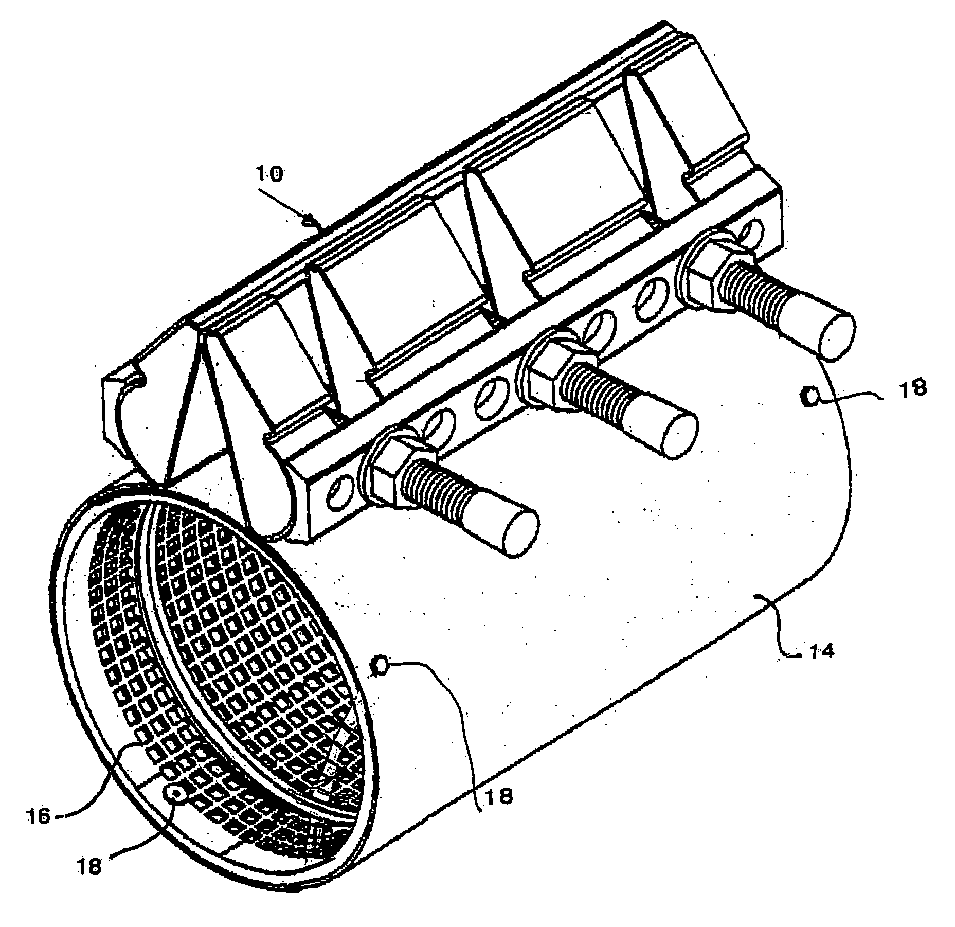
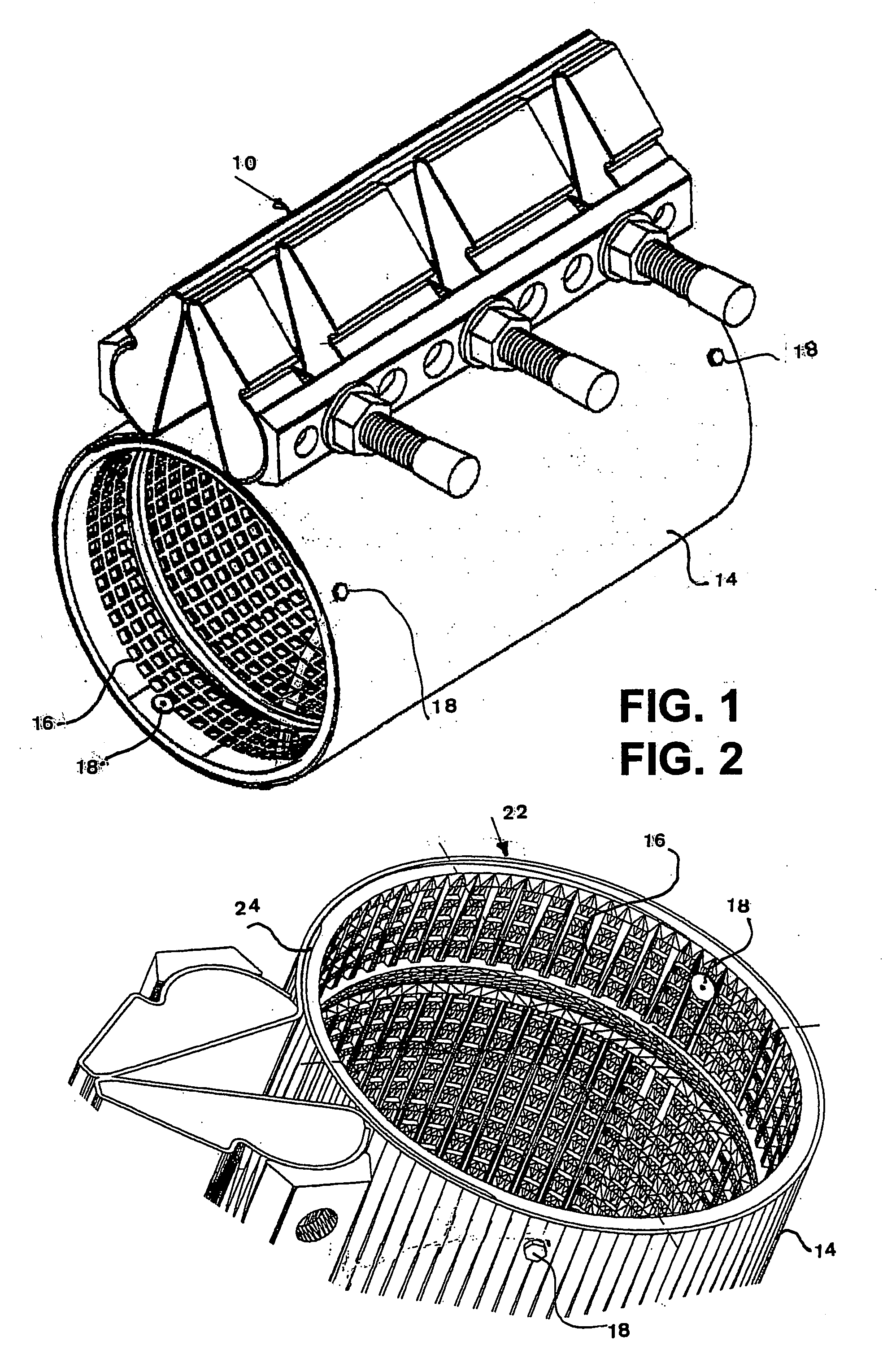
[0028] There is seen in FIG. 1 a pipe clamp or coupling 10 for sealing or for removably holding extremities of a pair of metallic pipes 12. The clamp force is provided by a metal clamping band 14 surrounding the pipe 12. A flexible inner sleeve 16 is disposed between the pipe 12 and the clamping band 14.

[0029] The inner sleeve 16 is attached to the clamping band 14 by means of a first plurality of metallic fasteners 18. The fasteners 18 are arranged to contact and press against the metallic pipe 12 when the band 14 is tightened, consequently forming a continuous electrical connection of the pipes. In one of our co-pending applications the sleeve is formed of a rolled-up mat. The fasteners 18 then serve to retain of one of the ends of the mat in the correct position relative to the clamping band 14.

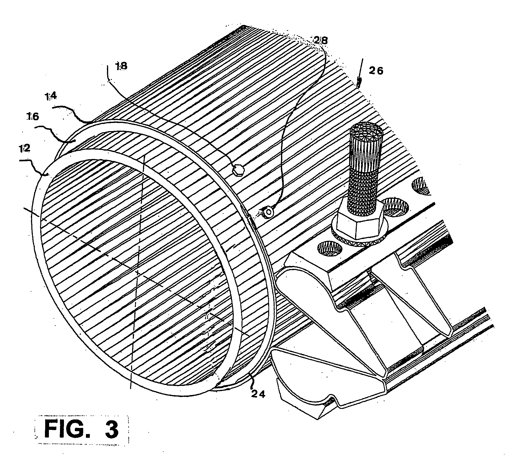
[0030] With reference to the rest of the figures, similar reference numerals have been used to identify similar parts.

[0031] Referring now to FIG. 2, there is again seen a pipe clamp or co...


PUM


Abstract

The present invention relates to the corrosion protection of a steel pipeline, and to improvements in pipe clamps useful for this purpose. The invention provides a pipe clamp or coupling which makes electric contact with the pipes on which it is assembled and provides a continuous electrical connection, of the pipes. The pipe clamp according to the invention for sealing by means of a metal clamping band to surround the pipe or a pipe coupling for removably holding extremities of a pair of metallic pipes provided with a flexible inner sleeve disposed inside the clamping band; the inner sleeve is attached to the clamping band by means of metallic fasteners, the metallic fasteners being arranged to contact the metallic pipes when the assembly is tightened, to form a continuous electrical connection of the pipes.

Description

[0001] This application claims priority of IL Patent Application No. 153271, filed Dec. 4, 2002, which is hereby incorporated by reference.FILED AND BACKGROUND OF THE INVENTION[0002] The present invention relates to the corrosion protection of a steel pipeline, and to improvements in pipe clamps useful for this purpose.[0003] More particularly, the invention provides a pipe clamp or coupling which makes electric contact with the pipes on which it is assembled and provides a continuous electrical connection, of the pipes.[0004] Whether steel pipelines are placed underground or above ground, they are subject to corrosive attack. Below ground the steel is attacked by various soil substances, particularly carbonaceous materials and acid wastes. Above ground the typical causes of corrosion are atmospheric moisture in combination with various air pollutants.[0005] A reliable method of resisting corrosion damage is to electrically connect the pipeline to a sacrificial zinc anode, the pipel...

Claims


Application Information

Patent Timeline
Patent Type & Authority Applications(United States)
IPC IPC(8): F16L55/172
CPCF16L55/172F16L25/01F16L58/185
Inventor KRAUSZ, ELIEZERCHIPROOT, AVI
Owner KRAUSZ IND
Why Eureka
Try Eureka