Paper transport apparatus and paper transport method

a technology of paper transport and paper transport, which is applied in the field of paper transport, can solve the problems of reducing the transfer efficiency or efficiency of the transfer operation, reducing the print quality,

Active Publication Date: 2004-06-17
SHARP KK
View PDF1 Cites 7 Cited by
  • Summary
  • Abstract
  • Description
  • Claims
  • Application Information

AI Technical Summary

Benefits of technology

[0016] A paper transport apparatus in accordance with one or more embodiments of the present invention comprises photosensitive body or bodies serving as image carrier(s) carrying toner; transfer roller(s) serving as transfer means, rotating and coming in contact with such photosensitive body or bodies, for causing toner image(s) formed on the photosensitive body or bodies to be electrostatically relocated onto paper; and paper transport means disposed upstream in transport direction(s) from such transfer roller(s) and comprising drive roller(s) and idler roller(s) holding lead edge portion(s) of paper in nip(s) formed therebetween and rotating so as to cause transport of same; the paper transport apparatus being constituted such that paper transport means is or are disposed to the side, on which photosensitive body or bodies is or are present, of a plane more or less tangent to nip(s) formed between photosensitive body or bodies and transfer roller(s); and direction(s) of transport of paper from paper transport means is or are disposed so as to be directed toward transfer roller(s). In accordance with one or more embodiments of the present invention, by thus causing lead edge(s) of paper transported from paper transport means to be directed toward transfer roller(s), it is possible to avoid situations in which the lead edge of the paper hits the photosensitive body surface such that a certain angle is formed therebetween.
[0017] In addition to the foregoing constitution, in one or more embodiments of the present invention, voltage(s) opposite in polarity to electrostatic potential(s) of photosensitive body or bodies may be applied to idler roller(s). By so doing, when lead edge(s) of paper approach vicinity or vicinities of point(s) at which contact is made with photosensitive body or bodies, lead edge(s) of paper charged with opposite polarity will be electrically drawn toward photosensitive body surface(s), permitting lead edge(s) of paper to be drawn toward photosensitive body surface(s) in smooth fashion. That is, because force(s) with which lead edge(s) of paper hit photosensitive body surface(s) is or are reduced, deterioration of photosensitive body or bodies can be prevented before it occurs, increasing photosensitive body life and making it possible to achieve stable print quality.
[0018] Furthermore, in one or more embodiments of the present invention, voltage(s) may be applied to idler roller(s), with no voltage(s) being applied to drive roller(s). If voltage(s) were to be applied to drive roller(s), talc or other such paper dust present in or on paper might be deposited due to applied voltage(s) from paper as it is held in nip(s) formed between the two rollers or sets of rollers, lowering transfer efficiency or efficiencies during transfer operation(s) and tending to cause decrease in print quality. While this is also true when voltage(s) is or are applied to idler roller(s), when voltage(s) is or are applied to idler roller(s), because talc or other such paper dust is deposited at back side(s) of photosensitive roller(s), there is no lowering of transfer efficiency or tendency to cause decrease in print quality.
[0019] Furthermore, in one or more embodiments of the present invention, drive roller(s) may comprise metal roller(s), and / or idler roller(s) may comprise electrically conductive elastic roller(s). Constituting respective roller(s) in such fashion permit smooth transport of charged paper and makes it possible to eliminate situations in which paper fails to separate from and becomes wrapped around roller(s) and / or transport problems or the like arising due to electrostatic force(s). Furthermore, employment of elastic roller(s) (electrically conductive rubber, foam resin, etc.) as idler roller(s) makes it possible to ensure definitive formation of nip region(s) (region(s) at which paper is held) between drive roller(s) and idler roller(s), and permits accurate application of voltage(s) to paper.
[0020] In such case, application of voltage(s) to idler roller(s) may be timed relative to holding of lead edge portion(s) of transported paper by nip(s) formed between drive roller(s) and idler roller(s). That is, what requires a soft landing (electrical attraction) with respect to the photosensitive body is the lead edge of the paper. Accordingly, there is no need to constantly apply voltage(s) to idler roller(s). Furthermore, drive roller(s) and idler roller(s) are paused with lead edge(s) of paper held in nip(s) formed between the two rollers or sets of rollers in order to cause lead edge(s) of paper to be aligned with lead edge(s) of image(s), and because width(s) of such nip(s) (length(s) in paper transport direction(s)) is or are constant regardless of the type of paper, application of voltage(s) timed relative to holding of lead edge portion(s) by nip(s) formed therebetween permits definitive charging of lead edge portion(s) of paper.
[0024] For example, if photosensitive body surface potential is 800 V and development bias is 400 V, application of a voltage of 800 V or more to charge the paper will result in very good nip entry phenomena between paper and photosensitive body, but because the toner on the photosensitive body "sees" a greater attractive force from the paper than the electrostatic force between the toner and the photosensitive body, toner will adhere to the paper lead edge void area before the transfer region can be reached. For this reason, irregular printing and / or soiling of lead edge void area(s) will tend to occur. In order to eliminate such phenomena, it is desirable to apply voltage(s) more or less equal in magnitude to electric potential(s) which when applied to developer unit(s) would cause latent electrostatic image(s) on photosensitive body or bodies to become visible. That is, the development bias is a bias potential set so as to cause developer material to adhere or not adhere to the photosensitive body depending upon whether image information is present. In one or more embodiments of the present invention, because paper lead edge void area(s) is or are non-imaged region(s), attraction of toner thereto must be avoided, and it is moreover necessary to cause paper to experience soft landing(s) at photosensitive body or bodies. Accordingly, by causing voltage(s) applied to idler roller(s) to be more or less equal in magnitude to development bias(es), it is possible to cause soft landing(s) at photosensitive body or bodies, and it is also possible to eliminate occurrence of printing troubles before they occur.

Problems solved by technology

If voltage(s) were to be applied to drive roller(s), talc or other such paper dust present in or on paper might be deposited due to applied voltage(s) from paper as it is held in nip(s) formed between the two rollers or sets of rollers, lowering transfer efficiency or efficiencies during transfer operation(s) and tending to cause decrease in print quality.

Method used


Image

  • Paper transport apparatus and paper transport method
  • Paper transport apparatus and paper transport method
  • Paper transport apparatus and paper transport method

Examples


Embodiment Construction

[0033] Below, embodiments of the present invention are described with reference to the drawings. Description of the present embodiment is carried out in terms of a situation in which a paper feed apparatus associated with the present invention is installed in a digital copier.

DESCRIPTION OF OVERALL CONSTITUTION OF COPIER

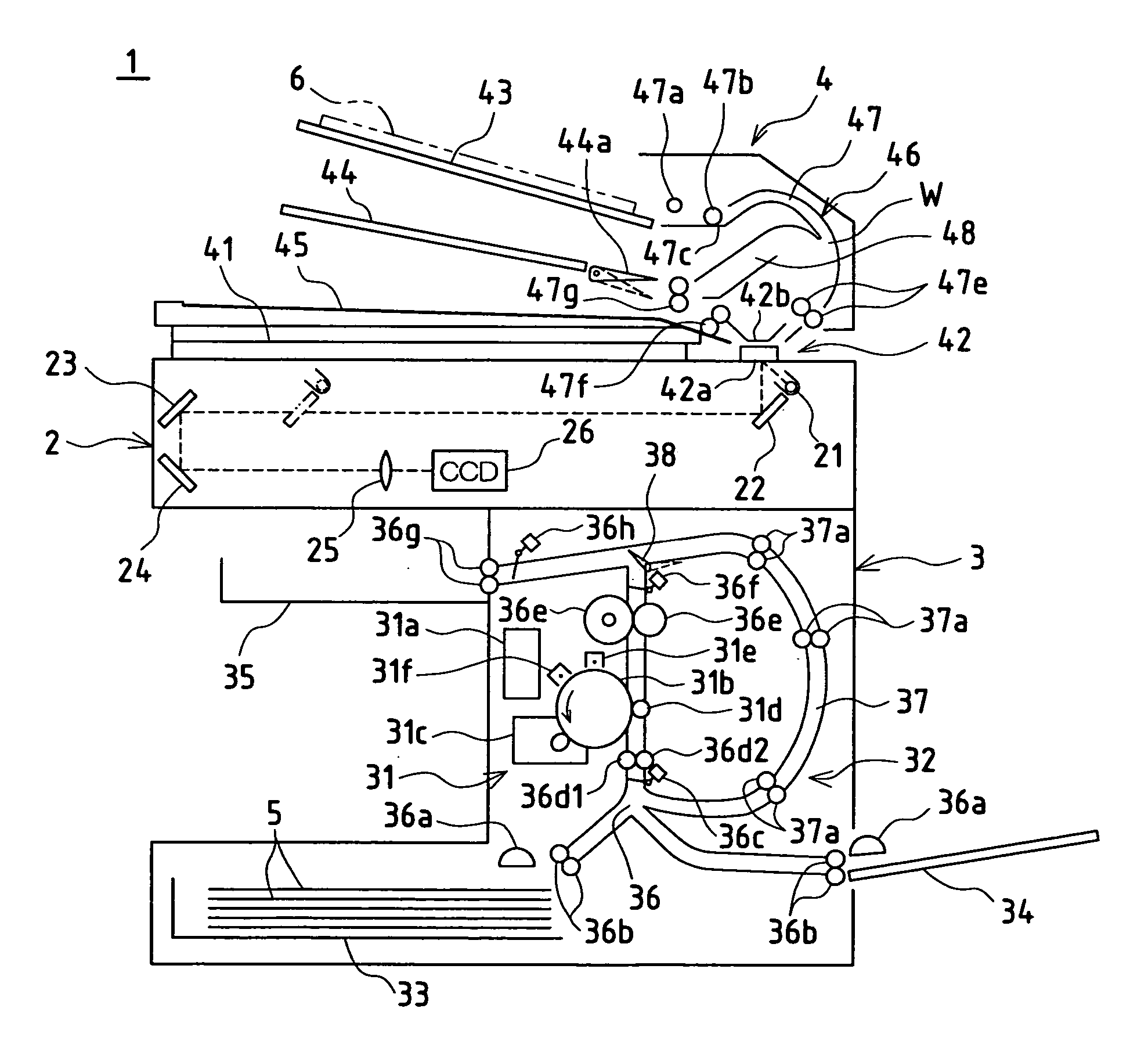
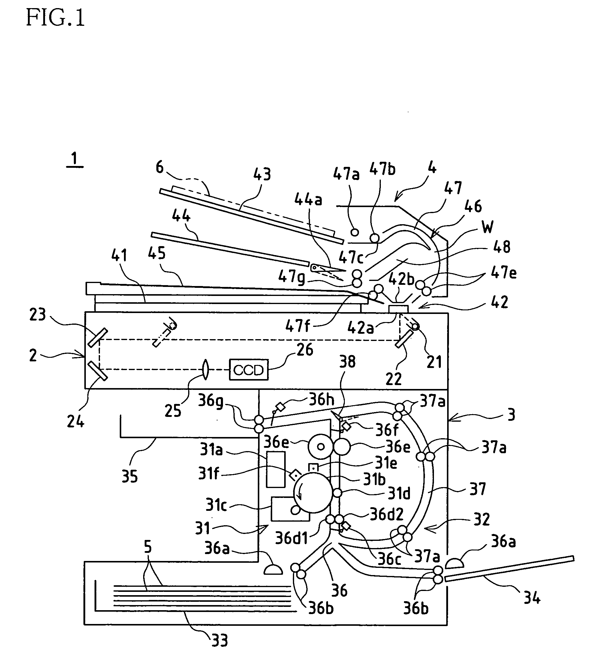
[0034] FIG. 1 shows in schematic fashion the internal constitution of copier 1 associated with the present embodiment. The present copier 1 is provided with scanning unit 2, printing unit 3 serving as image forming unit, and automatic original feed unit 4. Description of the respective units follows below.

[0035] Description of Scanning Unit 2

[0036] At the subassembly represented by scanning unit 2, images of originals placed on original stage 41 comprising transparent glass or the like and / or images of originals fed one at a time from automatic original feed unit 4 are captured and image data is created. This scanning unit 2 is provided with exposing light source 21;...


PUM


Abstract

Provided are photosensitive body or bodies 31b carrying toner; transfer roller(s) 31d, rotating and coming in contact with photosensitive body or bodies 31b, for causing toner image(s) formed on photosensitive body or bodies 31b to be electrostatically relocated onto paper 5; and paper transport means disposed upstream in transport direction(s) from transfer roller(s) 31d and comprising drive roller(s) 36d1 and idler roller(s) 36d2 holding lead edge portion(s) 5a of paper 5 in nip(s) formed therebetween and rotating so as to cause transport of same; drive roller(s) 36d1 and idler roller(s) 36d2 being disposed to the side, on which photosensitive body or bodies 31b is or are present, of a plane L more or less tangent to nip(s) formed between photosensitive body or bodies 31b and transfer roller(s) 31d; and direction(s) R of transport of paper from drive roller(s) 36d1 and idler roller(s) 36d2 being disposed so as to be directed toward transfer roller(s) 31d.

Description

BACKGROUND OF INVENTION[0001] 1. Technical Field[0002] The present invention relates to paper transport in image forming apparatuses.[0003] 2. Conventional Art[0004] In the paper feed mechanism of an image forming apparatus, locations of drive roller and idler roller serving as paper transport means are fixed, and the direction of transport of paper fed therethrough is constant.[0005] FIG. 7 shows the structure of a paper feed mechanism in a conventional image forming apparatus.[0006] A conventional paper feed mechanism comprises photosensitive body 81 serving as image carrier carrying toner; transfer roller 82, rotating and coming in contact with photosensitive body 81, for causing a toner image formed on this photosensitive body 81 to be electrostatically relocated onto paper 91; and paper transport unit 83 disposed upstream in the transport direction from transfer roller 82 and comprising drive roller (PS roller) 83a and idler roller (PS roller) 83b holding paper 91 in a nip form...

Claims


Application Information

Patent Timeline
Patent Type & Authority Applications(United States)
IPC IPC(8): G03G21/00B65H5/00B65H5/06G03G15/00G03G21/14
CPCG03G15/235G03G15/6558
Inventor IWAKURA, YOSHIETOMIYORI, MINORUMURAKAMI, SUSUMUIZUMI, HIDESHI
Owner SHARP KK
Why Eureka
Try Eureka