Clamping apparatus

Active Publication Date: 2004-06-17
TYGARD MACHINE & MFG
View PDF18 Cites 56 Cited by
  • Summary
  • Abstract
  • Description
  • Claims
  • Application Information

AI Technical Summary

Problems solved by technology

With a clamping apparatus of the type in which clamping arms translate without pivoting, bearings for supporting the clamping arms can wear out over time, and when such wear occurs, it is difficult to guide the c

Method used


Image

  • Clamping apparatus
  • Clamping apparatus
  • Clamping apparatus

Examples


Embodiment Construction

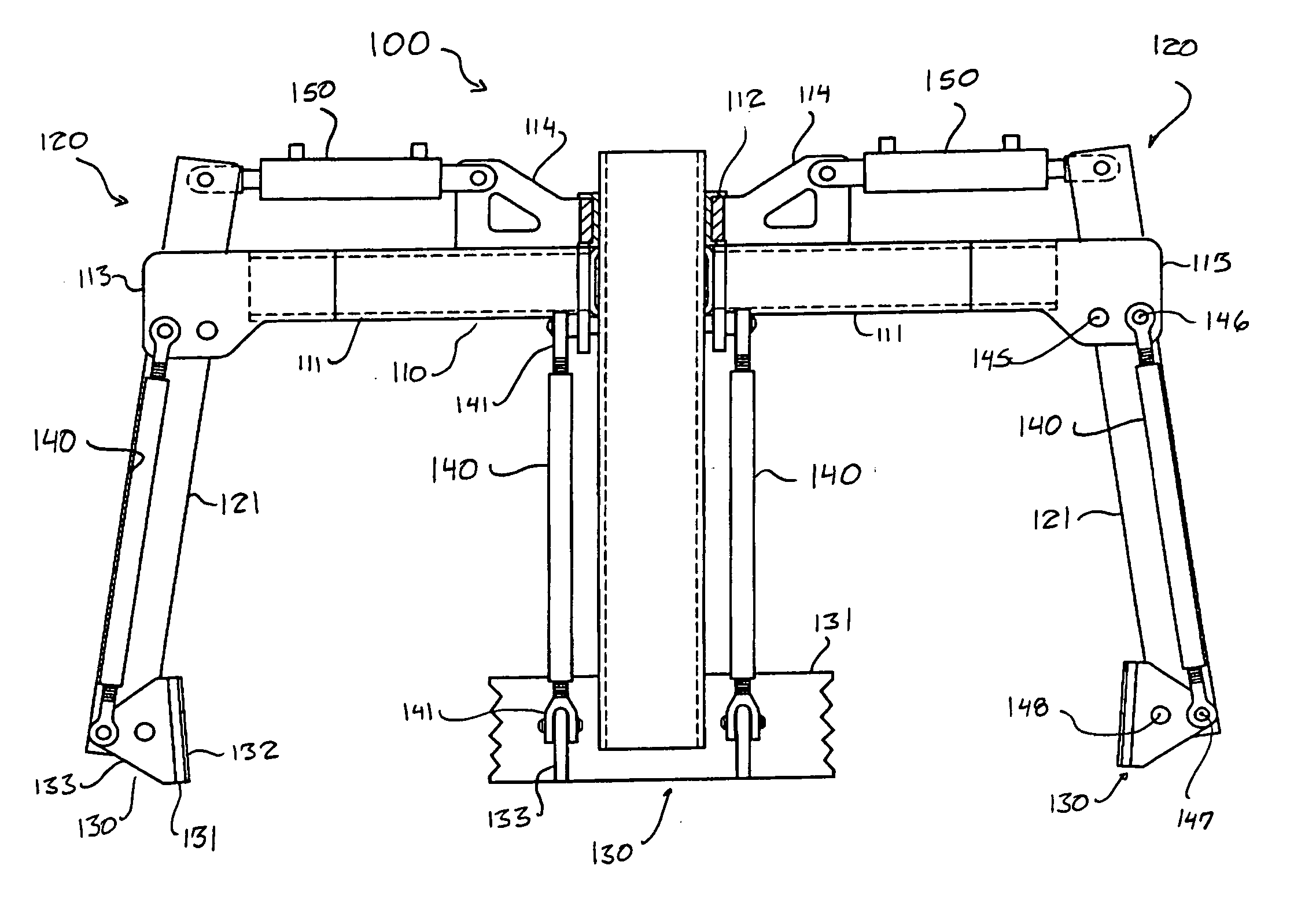
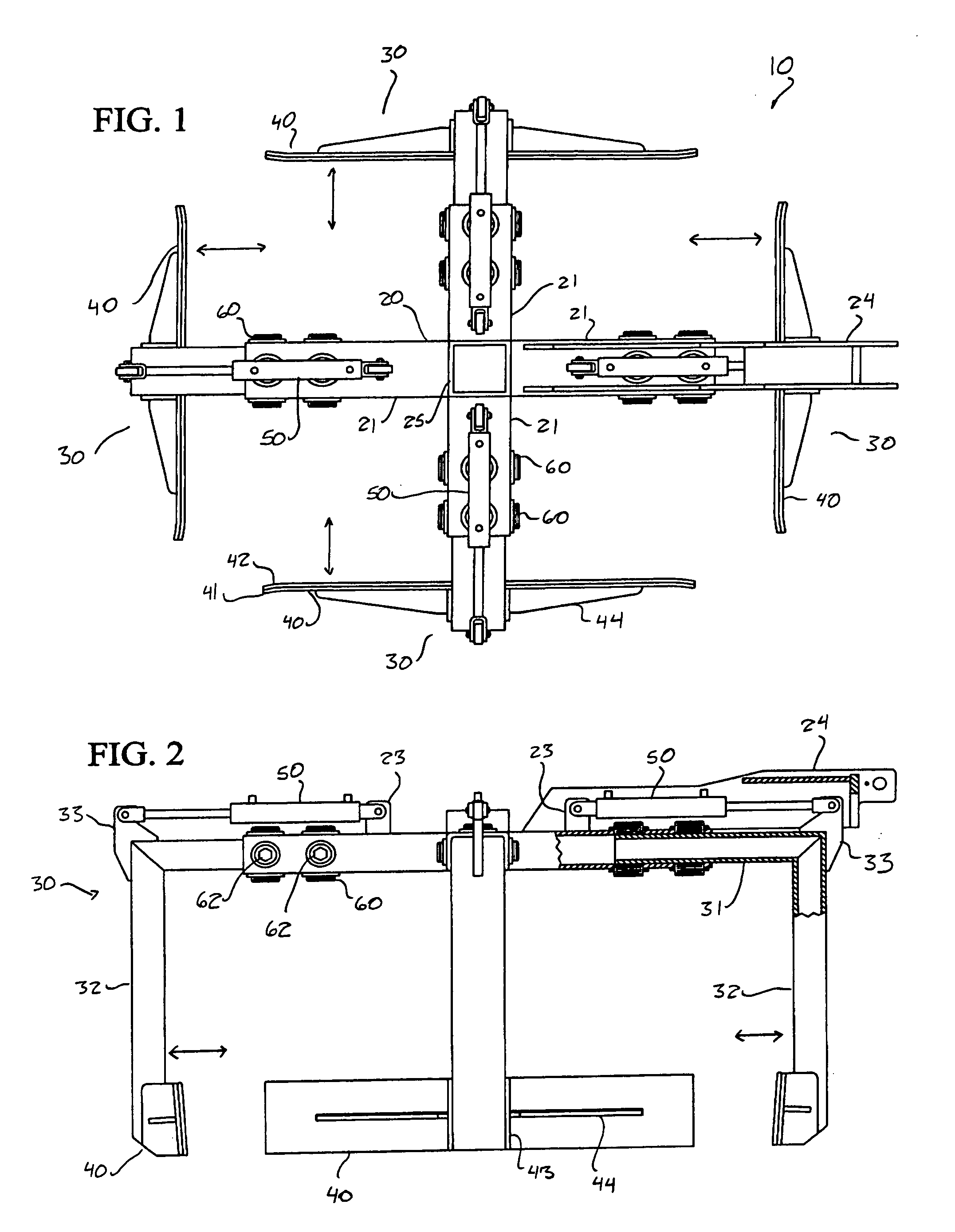
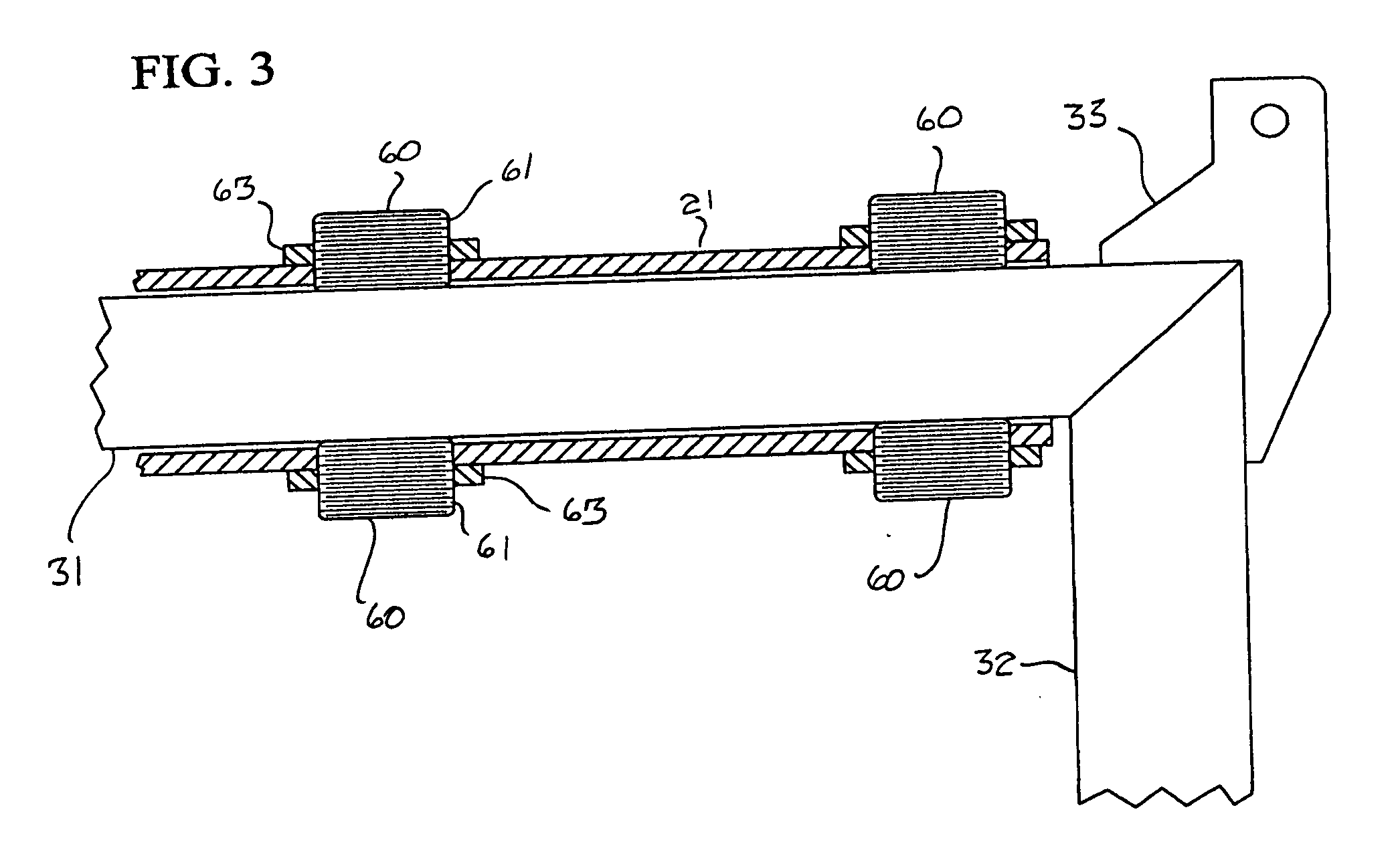
[0026] FIGS. 1-3 illustrate a first embodiment of a clamping apparatus 10 according to the present invention. This embodiment includes a frame 20 supporting a plurality of clamping arms 30 so as to enable opposing clamping arms 30 to translate with respect to each other to grasp or release a load. The frame 20 need not have any particular shape. In the present embodiment, the frame 20 is cross-shaped and has four tubular legs 21 disposed at right angles to each other. The inner end of each leg 21 is connected to a vertically extending rectangular guide tube 25 at the center of the frame 20. The guide tube 25 can be used to slidably receive an unillustrated internal support member for reinforcing the inner walls of a cavity in a layer of objects to be lifted by the clamping apparatus 10, as described in U.S. Pat. No. 6,003,917. However, if a support member is not needed, the guide tube 25 can be omitted, and the legs 21 can be directly connected to each other at their inner ends. The...


PUM


Abstract

A clamping apparatus includes a frame and a pair of opposing clamping arms mounted on the frame for movement towards and away from each other to grasp or release a load. In one embodiment, each clamping arm is guided for movement with respect to the frame by an adjustable bushing which can be rotated to adjust the position of the bushing with respect to the clamping arm. In another embodiment, each clamping arm defines a four-bar linkage which controls the angle with respect to the vertical of a contact portion of the clamping arm. The clamping apparatus may be mounted on a lift truck or other support member by a connector which permits the angle of the clamping apparatus with respect to the horizontal to be adjusted and which enables the clamping apparatus to pivot about an axis between a position in which it is disposed outboard of the axis and a position in which is it disposed forward of the axis.

Description

REFERENCE TO RELATED APPLICATIONS[0001] This application claims the benefit of U.S. Provisional Application No. 60 / 430,675 filed on Dec. 4, 2002 and U.S. Provisional Application No. 60 / 469,416 filed on May 12, 2003.[0002] 1. Field of the Invention[0003] This invention relates to a clamping apparatus for use in releasably grasping a load to be lifted from two or more sides. It also relates to an adjustable bushing suitable for slidably supporting a translating member, such as a clamping arm of a clamping apparatus.[0004] 2. Description of the Related Art[0005] Various clamping apparatuses have been developed for use in lifting loads. Among these clamping apparatuses are ones having a plurality of clamping arms which can releasably grasp a load to be lifted from multiple sides. In some cases, the clamping arms pivot between an open and closed position. In other cases, the clamping arms translate without pivoting along a linear or other path between an open and closed position.[0006] W...

Claims


Application Information

Patent Timeline
IPC IPC(8): B66C1/42
CPCB66C1/427Y10S414/11Y10S414/13
Inventor TYGARD, EDWARD
Owner TYGARD MACHINE & MFG
Why Eureka
Try Eureka