Stator for a rotary electric machine

a technology of rotary electric machines and rotors, which is applied in the direction of electrical equipment, dynamo-electric machines, supports/enclosements/casings, etc., can solve the problems of noisy rotary electric machines, heat given off in operation, and the need for cooling, so as to achieve good damping of noise and vibration

Inactive Publication Date: 2004-07-01
MOTEURS LEROY SOMER
View PDF14 Cites 45 Cited by
  • Summary
  • Abstract
  • Description
  • Claims
  • Application Information

AI Technical Summary

Benefits of technology

0008] The present invention sets out to provide a stator for a rotary machine that makes it possible to provide good damping of noise and vibration while, where appropriate, enabling a cooling circuit to be integrated in the casing of the stator.

Problems solved by technology

Rotary machines, and more particularly variable-reluctance rotary electric machines suffer from the drawback of being noisy because of the noise and vibration generated mainly by the stator.
Another problem associated with rotary machines, in particular variable-reluctance rotary electric machines, is the heat given off in operation which makes cooling necessary.
Such a ring is prejudicial to sound insulation of the motor since it conducts vibration.
In addition, the motor shown in FIG. 5 does not enable high torque to be transmitted between the stator and the casing.

Method used


Image

  • Stator for a rotary electric machine
  • Stator for a rotary electric machine
  • Stator for a rotary electric machine

Examples


Embodiment Construction

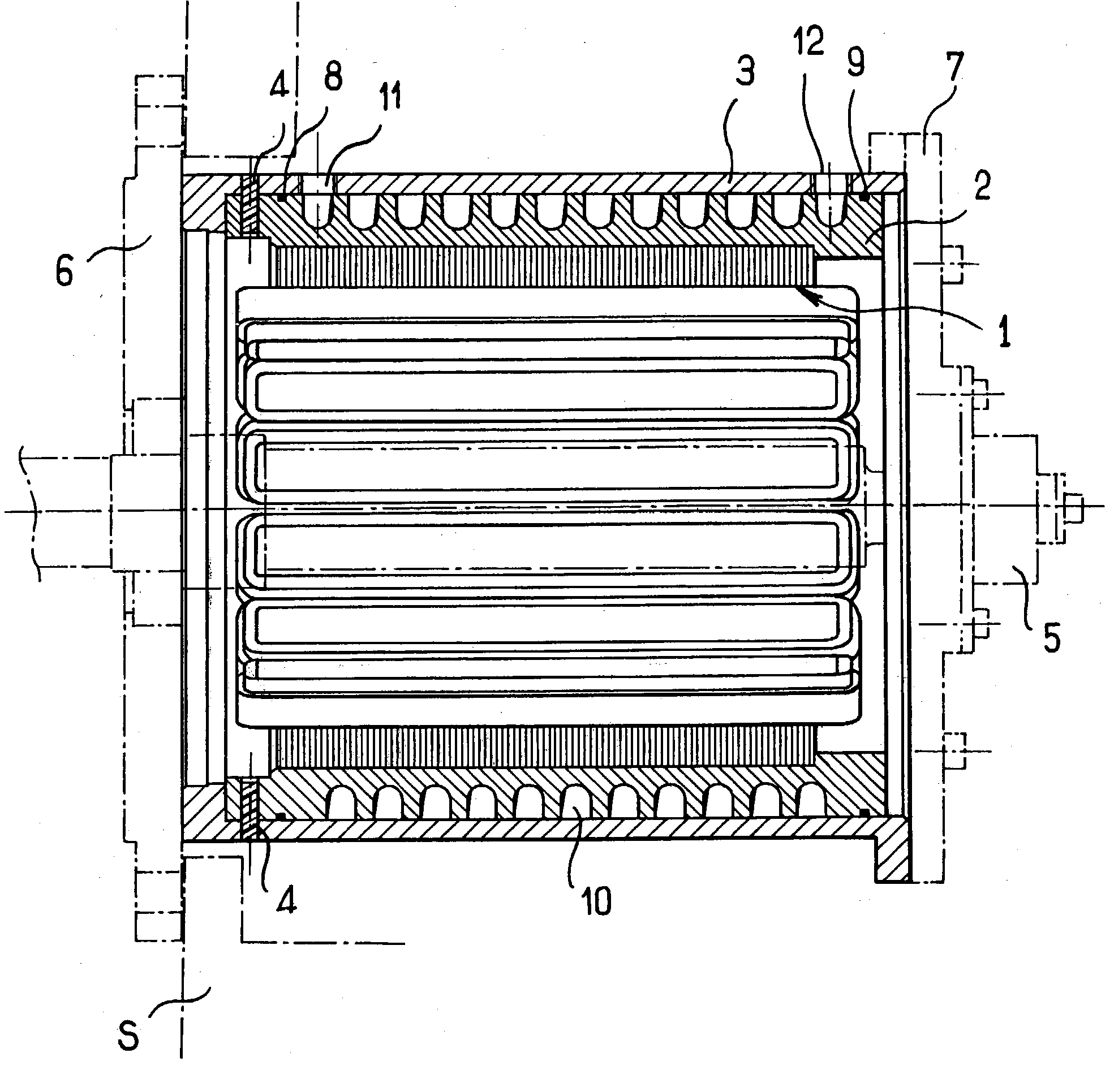
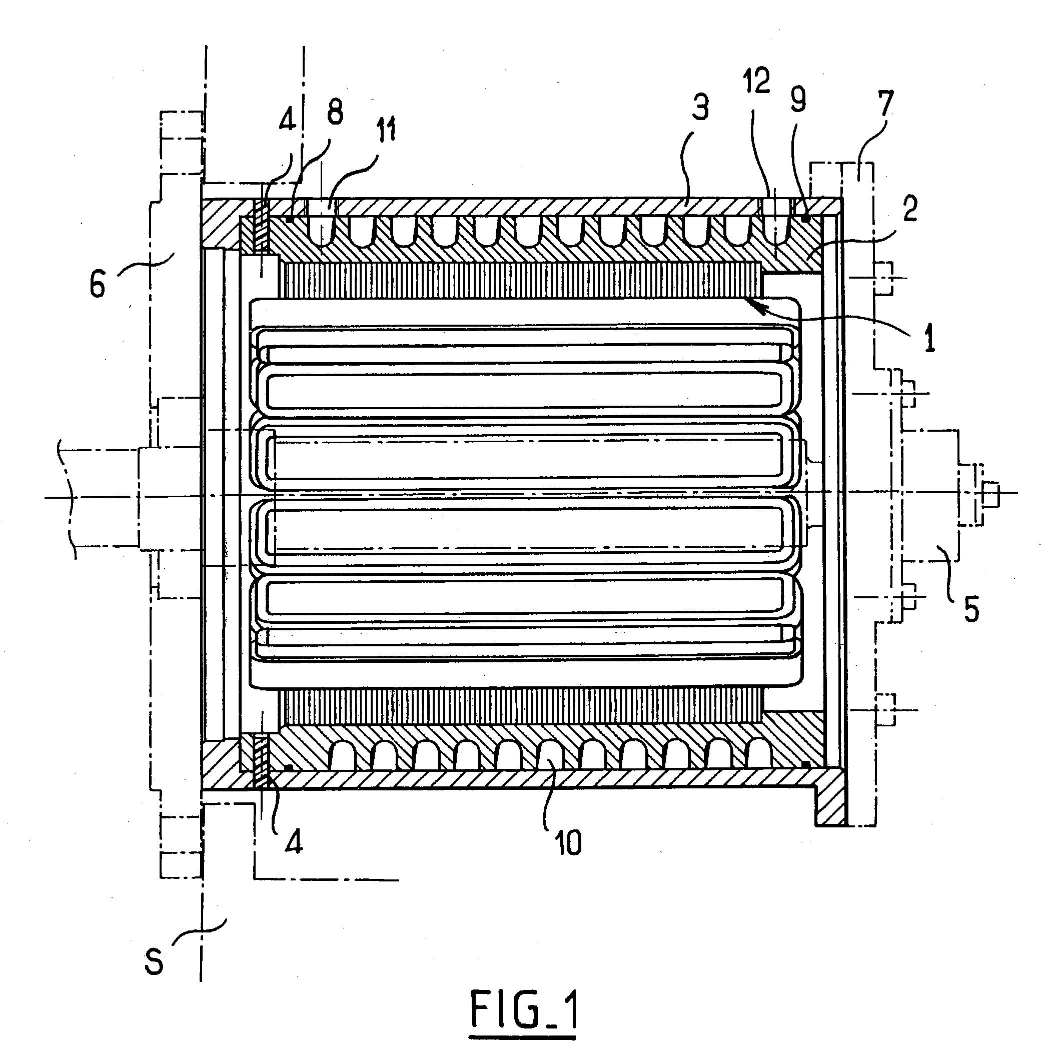
[0049] The stator shown in FIG. 1 comprises a stator body made up of a stack of stator magnetic laminations given overall reference 1, and an outer peripheral casing that may be constituted by an inner first part or yoke 2 and an outer second part or yoke 3, the inner part 2 being connected to the stator body 1 as an interference fit or by adhesive, for example.

[0050] The parts 2 and 3 constituting the stator casing are disposed concentrically leaving a small amount of clearance between their facing surfaces, for example clearance of about {fraction (1 / 10)} mm.

[0051] The parts 2 and 3 are positioned axially and in rotation by stop means 4 such as pins, screws, or pegs made at least in part out of damping materials. The stop means serve to transmit torque from the stator body to the outer part 3 of the casing.

[0052] In FIG. 1, chain-dotted lines 5??? represent the rotor 5 inside the stator, and end cheekplates 6 and 7 that act as bearings for the rotor, the stator casing being connec...


PUM


Abstract

The present invention relates to a stator for a rotary electric machine, the stator comprising a stator body made up of a stack of stator laminations and first and second nested concentric disposed with clearance about the stator body. First resilient damping elements are placed between the two parts. These resilient damping elements are disposed circumferentially around the inner one of said two parts between the outer surface of said inner part and the facing inner surface of the outer part. Relative movement between the two parts is limited both axially and circumferentially by second damping elements.

Description

[0001] The present invention relates to a stator for a rotary electric machine, for example a variable-reluctance motor.[0002] Rotary machines are essentially constituted by a rotor and a stator, the stator being connected to a host structure either directly or via cheekplates, while the rotor is mounted to rotate inside the stator.[0003] Rotary machines, and more particularly variable-reluctance rotary electric machines suffer from the drawback of being noisy because of the noise and vibration generated mainly by the stator.[0004] To filter and damp the noise and vibration generated by the stator of a rotary machine, EP-A-0 957 564 has already proposed making the magnetic circuit of the stator as two concentric cylindrical parts that are nested with clearance, said parts being held spaced apart from each other by a plurality of damping elements that are elongate, resilient, and extend in an axial direction, i.e. along generator lines of the two nested cylindrical parts constituting...

Claims


Application Information

Patent Timeline
Patent Type & Authority Applications(United States)
IPC IPC(8): H02K5/20H02K5/24
CPCH02K5/24H02K5/20H02K5/203
Inventor CONDAMIN, DOMINIQUEGASTE, JEANMURZEAU, PHILIPPEBOULAI, ERIC
Owner MOTEURS LEROY SOMER
Why Eureka
Try Eureka