Plasma display panel

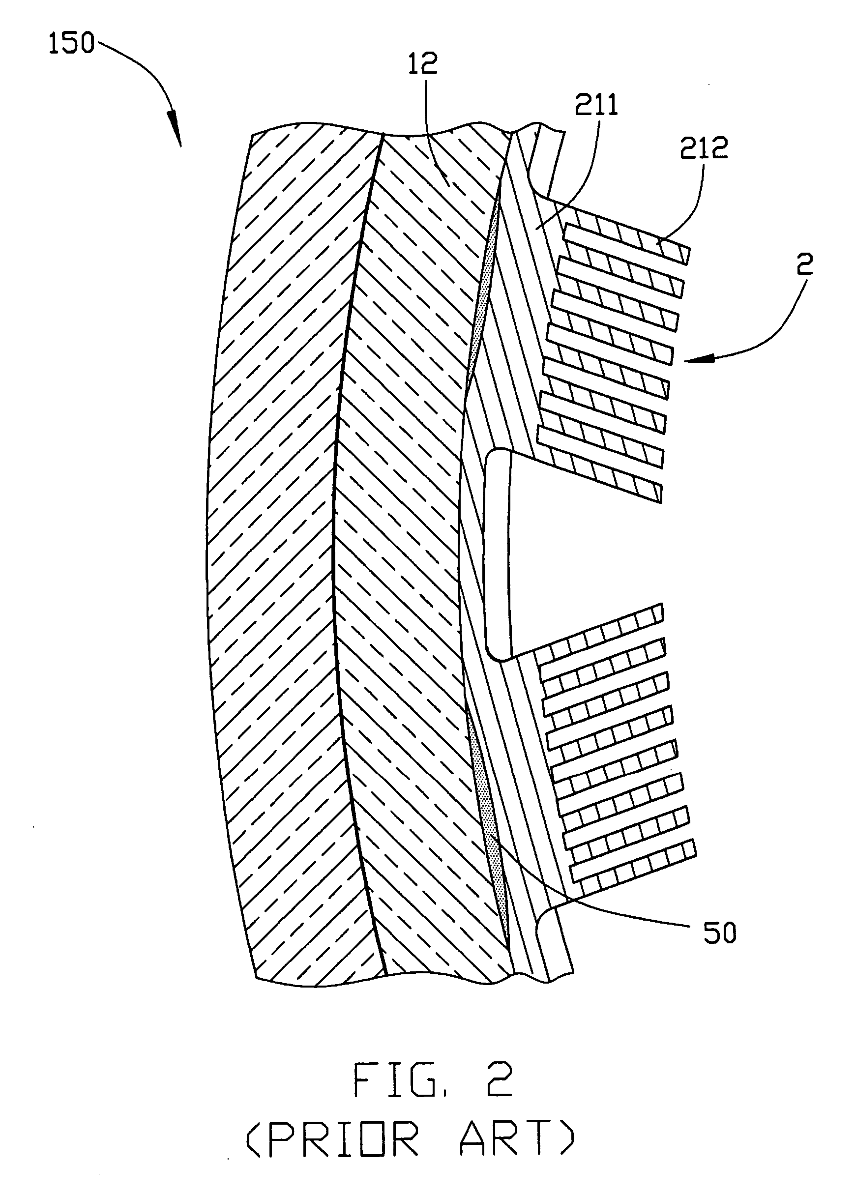
a technology of display panel and plasma, which is applied in the direction of incadescent cooling arrangement, nanoinformatics, discharge tube main electrodes, etc., can solve the problems of poor heat conductivity of the adhesive layer 50, the temperature of the panel unit to rise, and the discharge cell tends to exacerbate the breakage problem

Inactive Publication Date: 2004-07-01
HON HAI PRECISION IND CO LTD
View PDF6 Cites 60 Cited by
  • Summary
  • Abstract
  • Description
  • Claims
  • Application Information

AI Technical Summary

Problems solved by technology

The discharge cells in the plasma display panel generate heat when they emit light for image formation, which causes the temperature of the panel unit to rise.
And the discharge cells tend to exacerbate the breakage problem of the panel unit of the plasma display panel.
However, the heat conductivity of the

Method used


Image

  • Plasma display panel
  • Plasma display panel
  • Plasma display panel

Examples


Embodiment Construction

)

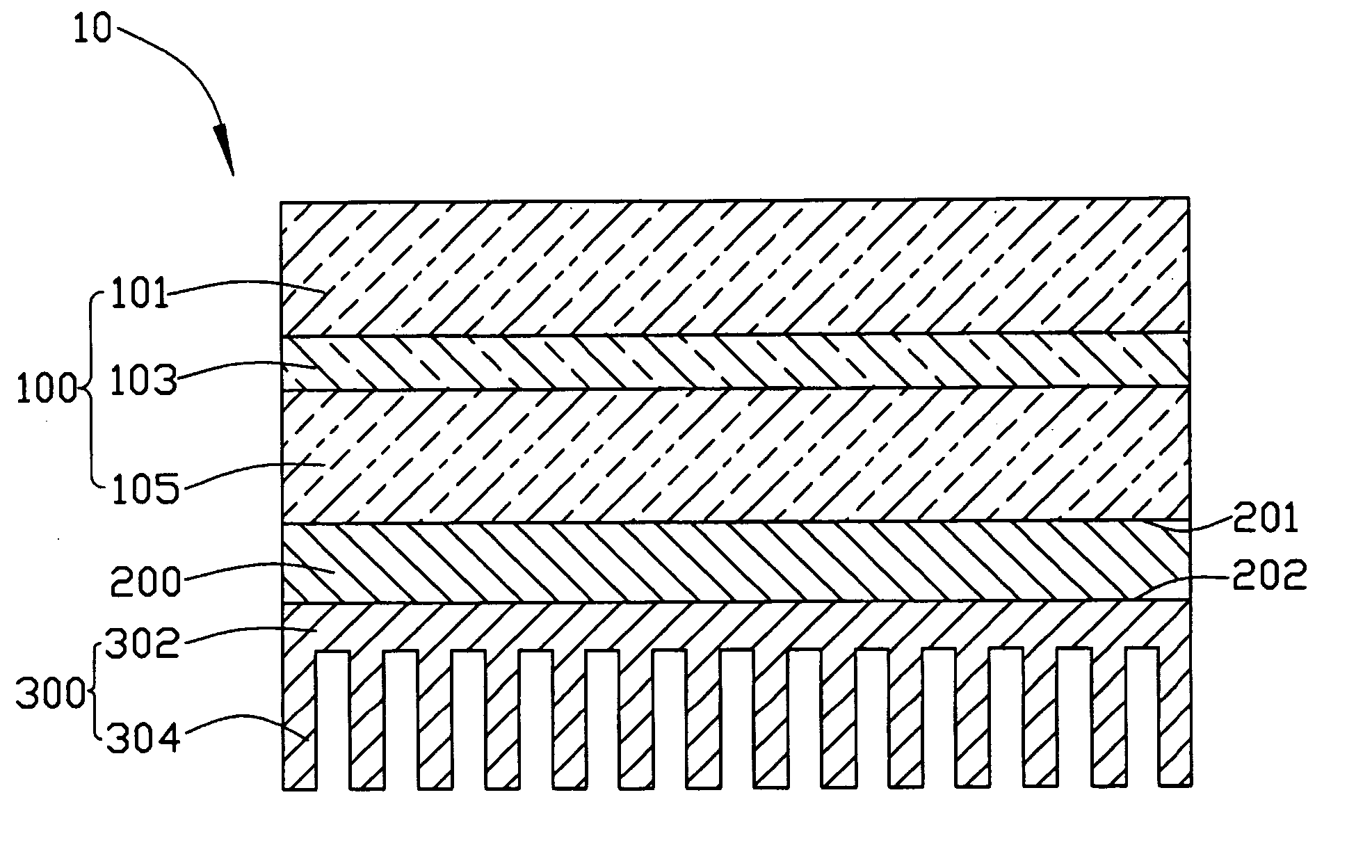
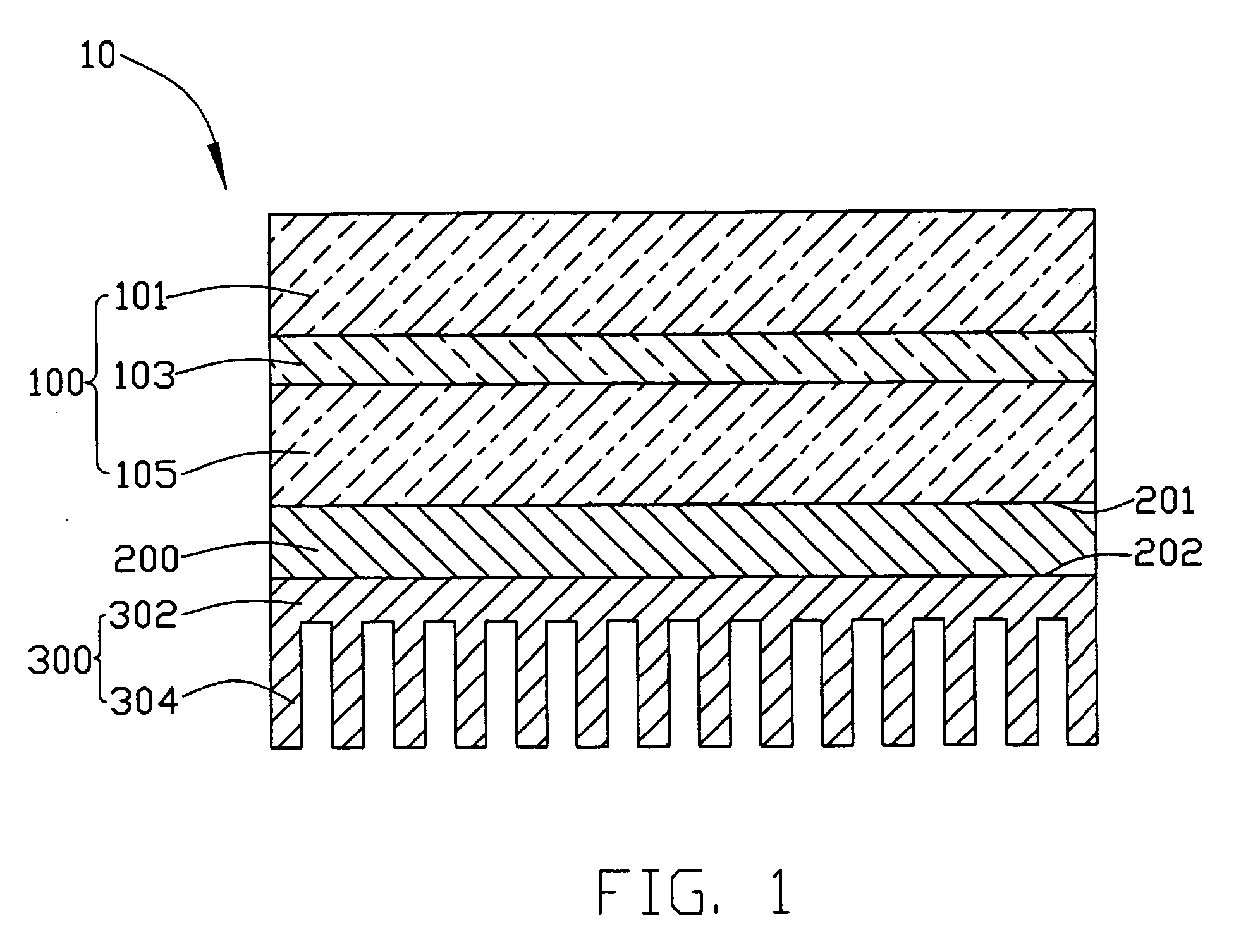
[0014] FIG. 1 shows a cross-sectional view of a plasma display panel 10 of a preferred embodiment in accordance with the present invention. The plasma display panel 10 includes a panel unit 100, a thermal interface 200 and a heat sink unit 300. The thermal interface 200 is interposed between the panel unit 100 and the heat sink unit 300.

[0015] The panel unit 100 comprises a front substrate 101, a back substrate 105 and a plurality of discharge cells 103 between the front substrate 101 and the back substrate 105. The discharge cells 103 are arranged horizontally and vertically in a matrix array manner. The panel unit 100 is about 5 millimeters in thickness. A plurality of flexible circuit boards (not shown) are provided which connect to electrodes from the discharge cells 103 to electrically drive the panel unit.

[0016] The thermal interface 200 is made of a thermal interface material having a plurality of carbon nanotubes (not shown), and the thermal interface 200 has a first surfac...


PUM


Abstract

The present invention provides a plasma display panel (10), which includes a panel unit (100) containing a large number of discharge cells (103), a heat sink unit (300) bonded along a back substrate (105) of the panel unit for dissipating heat generated by the panel unit, and a thermal interface (200) interposed between the panel unit and the heat sink unit for connecting the panel unit and the heat sink unit. The thermal interface is made of a thermal interface material including carbon nanotubes. The heat sink unit includes a substrate (302) and a plurality of fins (304), wherein the substrate is formed from an anisotropic material for transferring the heat from the panel unit to the fins of the heat sink unit. The plasma display panel thus has high heat conductive performance.

Description

[0001] 1. Field of the Invention[0002] The present invention relates to a plasma display panel having high heat conductive performance.[0003] 2. The Related Art[0004] Plasma display panels are widely used in applications such as gasoline dispensers. The plasma display panel comprises a panel unit containing a plurality of discharge cells. The panel unit emits light beams to display an image when a voltage is applied across electrodes of each of a selected group of discharge cells. The panel unit, which is the main part of the plasma display panel, is fabricated by bonding two glass base plates together in such a manner as to sandwich the discharge cells therebetween.[0005] The discharge cells in the plasma display panel generate heat when they emit light for image formation, which causes the temperature of the panel unit to rise. As a brightness of the discharge cells increases, the amount of heat generated in the discharge cells also increases. And the discharge cells tend to exace...

Claims


Application Information

Patent Timeline
IPC IPC(8): H01J17/28H05K7/20
CPCB82Y10/00H05K7/20963H01J2217/492
Inventor CHEN, GA-LANE
Owner HON HAI PRECISION IND CO LTD
Why Eureka
Try Eureka