
Operating-microscope system

a microscope and operating system technology, applied in the field of operating microscope systems, can solve the problems of complicated positioning of the microscope, the surgeon usually has to put down the operating instrument, and the foot switch cannot be used in the sitting position

Inactive Publication Date: 2004-07-01
MOELLER WEDEL GMBH
View PDF7 Cites 14 Cited by
  • Summary
  • Abstract
  • Description
  • Claims
  • Application Information

AI Technical Summary

Benefits of technology

[0010] The object is achieved according to the invention in that the switch is designed as a sterilizable hand switch that can be arranged on the operating table. Since the switch can be arranged on the operating table, it is provided in very close proximity to the patient and / or the operating area, with the result that the operator can actuate the switch without putting down the operating instrument. It is also the case here that his / her hand does not become contaminated since the switch can be sterilized. This thus gives the advantage of particularly precise manual control without the disadvantages of the prior-art control means.
[0012] The switch may be provided with a heavy base, with the result that it cannot be easily displaced on the operating table. It is particularly expedient, however, that the switch have devices for fastening to the operating table, since there is then less risk of the switch being accidentally displaced.

Problems solved by technology

One disadvantage of this type of system is that the surgeon usually has to put down the operating instrument to make the adjustment.
Further, accurate positioning of the microscope is complicated by release of all the axes which allows the microscope to move in every direction.
In the case of foot switches, there is no need, for corrective purposes, to put down the operating instrument, but foot switches can only be used in the sitting position.
Here too, control usually takes place via hand switches, as a result of which the above-mentioned disadvantages cannot be avoided.
These techniques, however, have not gained widespread acceptance since they require too much concentration on the part of the surgeon and there is a risk of signals given being misinterpreted.
The switch may be provided with a heavy base, with the result that it cannot be easily displaced on the operating table.

Method used


Image

  • Operating-microscope system
  • Operating-microscope system
  • Operating-microscope system

Examples


Embodiment Construction

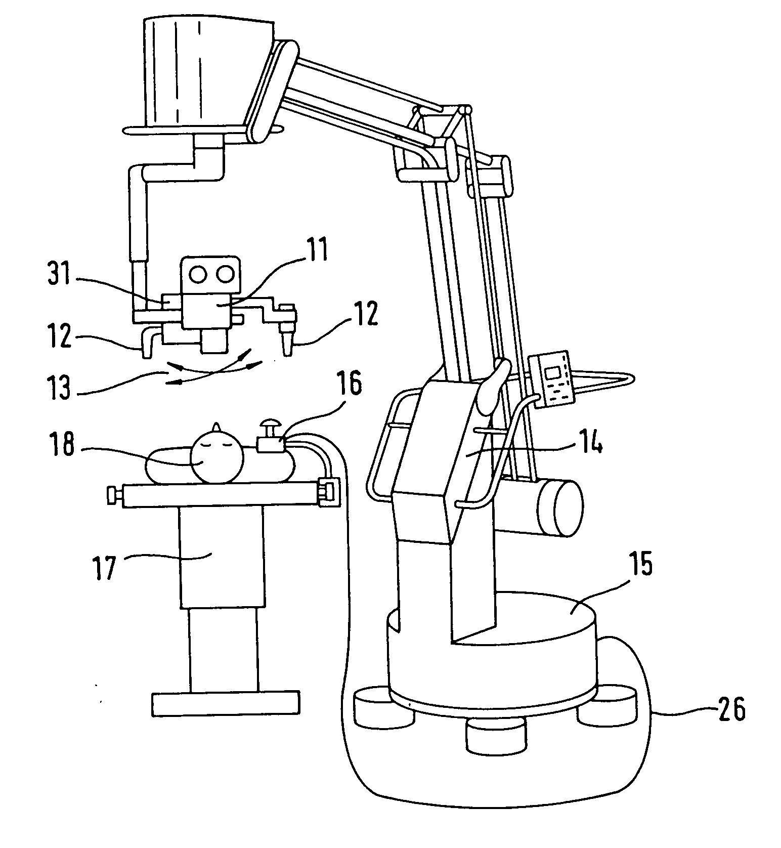
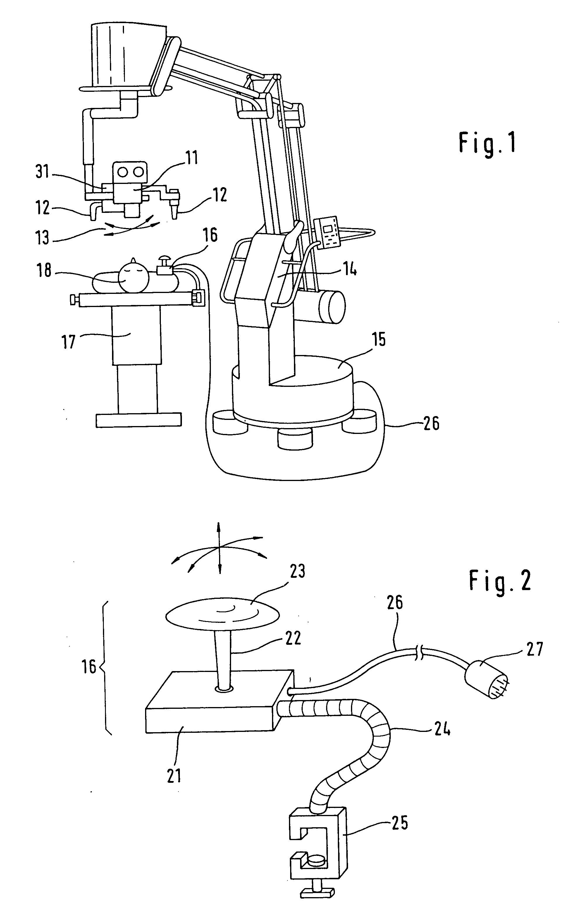
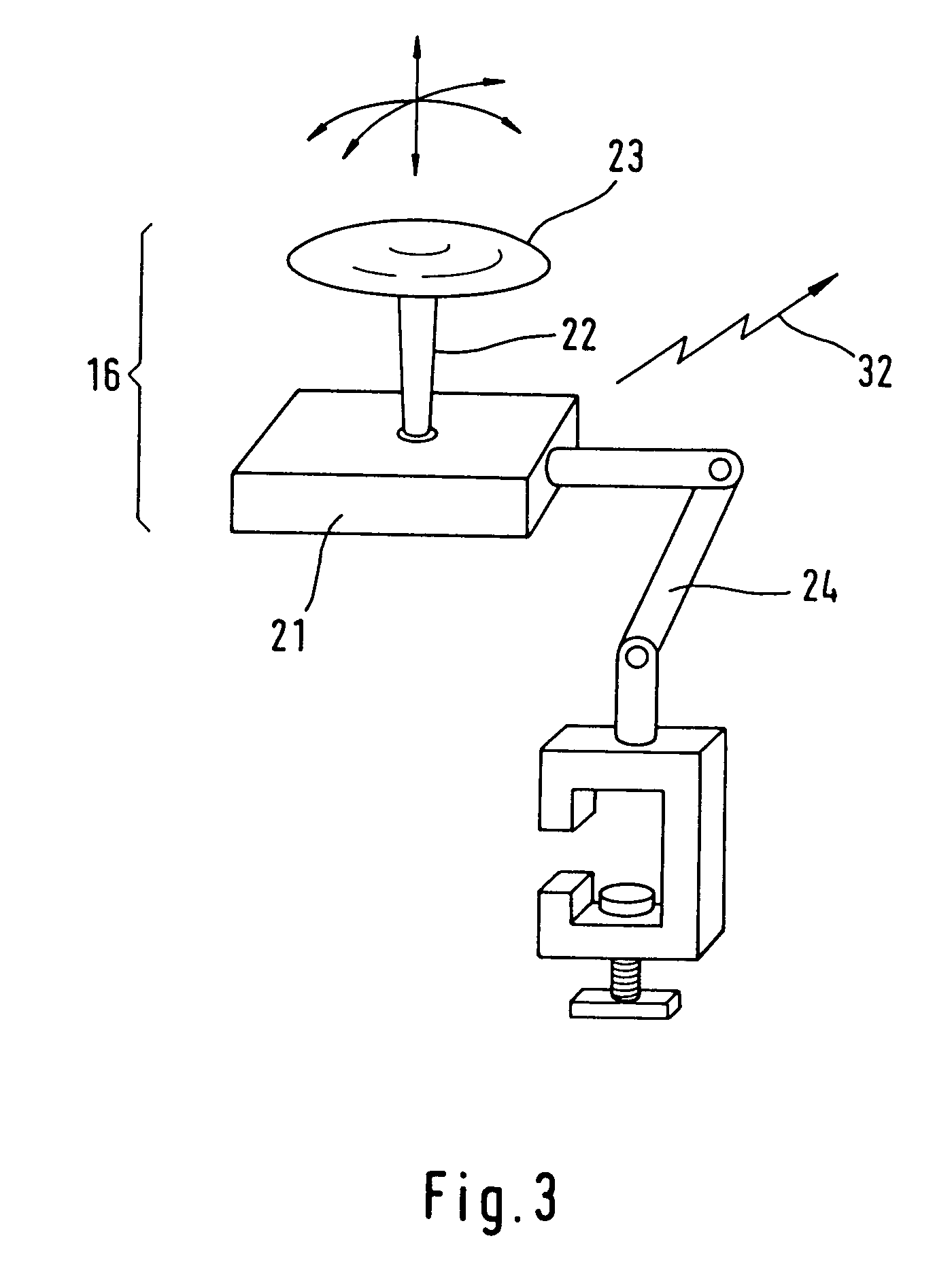
[0021] In FIG. 1, the operating microscope system includes an operating microscope 11, which is usually equipped with handles 12. The operating microscope 11 here is equipped with motors 31 for the rotary movements 13 and focusing purposes. For suspending the operating microscope 11 in space, use is made of the carrier system 14, which contains an electric supply unit 15 with an electrical connection for the motors. A hand switch 16 is fastened on the operating table 17, on which the patient 18 lies in accordance with aspects of the present invention. Fastening the hand switch 16 on the operating table 17 places the hand switch 16 in the vicinity of the operating area where it can be operated by the surgeon during the operation without him / her having to put down the operating instrument. The hand switch 16 may be connected to the supply unit 15 for the motors via a connecting cable 26 or a wireless connection 32.

[0022] FIG. 2 illustrates one embodiment of the hand switch 16. A lever...


PUM


Abstract

An operating-microscope system including an operating microscope, a carrier system for the microscope, and at least one drive element that can be actuated by a switch and is intended for moving and / or focusing a microscope includes a sterilizable hand switch arranged on the operating table. The switch is positioned and configured so that the surgeon may actuate the switch to move and / or focus the microscope without releasing the operating instrument.

Description

[0001] 1. Field of the Invention[0002] The invention generally relates to operating-microscope systems having an operating microscope, a carrier system for the microscope, and at least one drive element and more specifically to actuation switches for moving and / or focusing the microscope during surgery.[0003] 2. Description of the Related Art[0004] Operating microscopes are required for operations on fine biological structures such as the eye (opthalmology) or the brain and nervous system (neurosurgery). It is necessary for the position and focus of the operating microscope to be adjustable by the surgeon during surgery. These adjustments cannot require the surgeon to touch non-sterile surfaces.[0005] There are already operating microscopes which, by virtue of movable carrier systems and a movable microscope suspension, allow movement about 3 translational-movement axes and 3 axes of rotation. For this purpose, these microscopes have handles, which, as is also the case with the body...

Claims


Application Information

Patent Timeline
IPC IPC(8): A61B19/00
CPCA61B19/26A61B2019/4868A61B19/5223A61B19/52A61B90/36A61B90/25A61B90/50A61B2090/0813A61B90/20
Inventor SCHMIDT, MARTINSCHALT, PETER
Owner MOELLER WEDEL GMBH
Learn More