Self-leveling high heat transfer mold

a mold and heat transfer technology, applied in the field of planar mold design, can solve the problems of variable tooth pitch within one molded section of the belt, poor heat conduction, unacceptable over cure, etc., and achieve the effect of simple mold design, quick and easy adjustment, and minimized over cure risk

Inactive Publication Date: 2004-07-01
VEYANCE TECH
View PDF8 Cites 6 Cited by
  • Summary
  • Abstract
  • Description
  • Claims
  • Application Information

AI Technical Summary

Benefits of technology

0035] e) a pin in one or more of the heat transfer cavities of the center or end zones, said pin having a profile and size selected to change the film coefficients at any particular point along the extent of the cavity without modification to the cavity surfaces, said pin in contact or not in contact with the prime heat transfer surfaces of the cavity, depending on the desired effect of the pin on the fluid flow and convective heat transfer properties of the cavity, said pin mounted at its end or ends when not in contact with the prime heat transfer surfaces of the cavity, said pin allowing the mold to be designed with simple and economical heat transfer cavity shapes, and allowing tuning of the thermal response of the mold without modification of the heat transfer cavity.
0036] One advantage of this invention is that sections of a belt can be seq

Problems solved by technology

Temperature variations in the mold can require longer curing cycle times so that the coldest portion is fully cured, but longer curing cycle times can result in unacceptable over-cure in the hotter areas.
Temperature variation also causes variable thermal expansion of the mold and belt materials, which can cause variable tooth pitch wi

Method used


Image

  • Self-leveling high heat transfer mold
  • Self-leveling high heat transfer mold
  • Self-leveling high heat transfer mold

Examples


Embodiment Construction

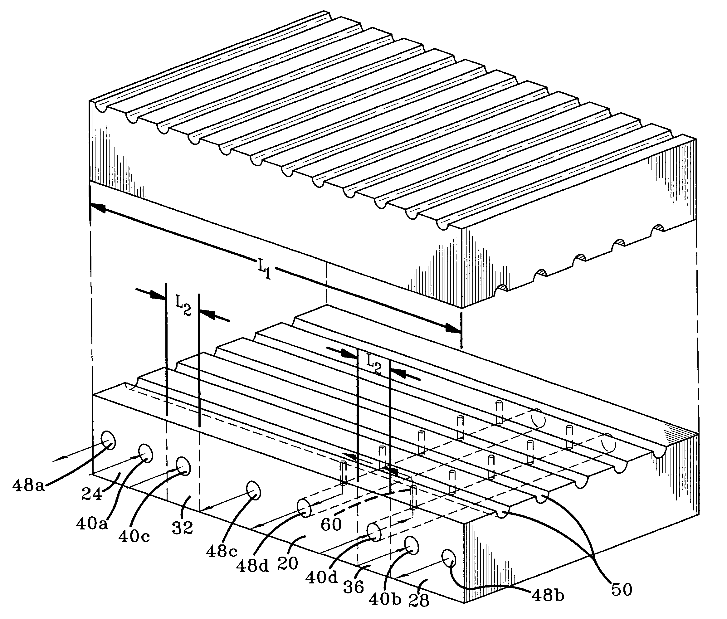
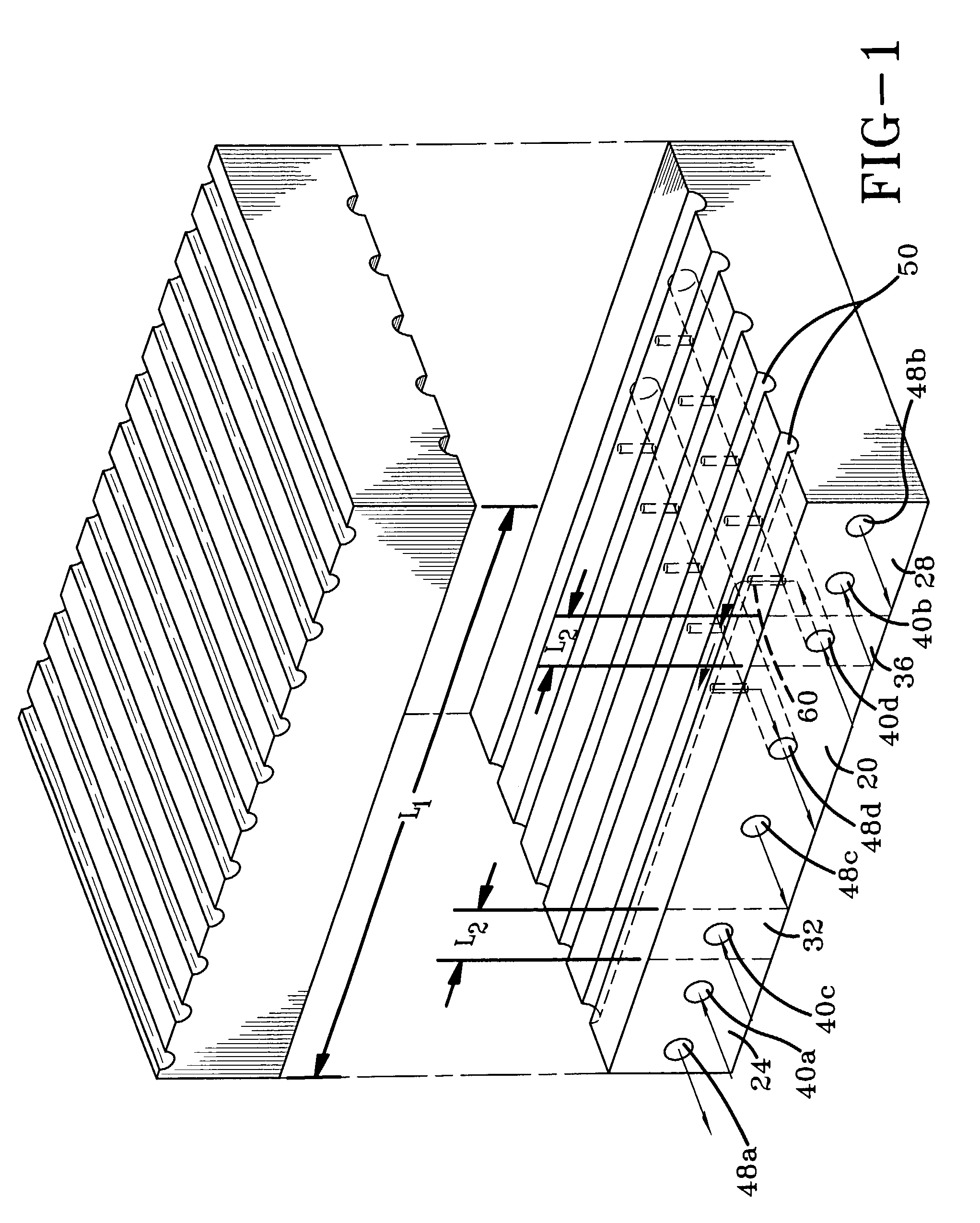
[0044] Referring now to the drawings wherein the showings are for purposes of illustrating a preferred embodiment of the invention only and not for purposes of limiting the same, FIG. 1 shows a mold half 10A. The principles governing the heating of a mold will be explained with reference to mold half 10A for the sake of simplicity. A mating mold half (not shown in this view) utilizes similar principles. A mold for curing a belt slab includes a length, L1, which in use is disposed along the circumference of the belt. The mold is characterized by a center zone 20, a first end zone 24, a second end zone 28, a first transition zone 32 disposed generally between the first end zone 24 and the center zone 20, and a second transition zone 36 disposed generally between the second end zone 28 and the center zone 20. Each of the transition zones 32, 36 has a mold length L2, which is less than L1. Transition zone length L2 is also less than the length of the center zone 20. As shown in FIG. 1, ...


PUM

PropertyMeasurementUnit
Temperatureaaaaaaaaaa
Lengthaaaaaaaaaa
Widthaaaaaaaaaa

Abstract

A mold for sequentially curing sections of a belt includes two end zones, a center zone, and transition zones between each end zone and the center zone. The mold is heated and/or cooled by heat transfer fluid flowing from intake manifolds through heat transfer cavities. The intake manifolds are preferably arranged perpendicular to the mold length. In the end zones and in the center zone, the heat transfer cavities are arranged substantially parallel to the length of the mold. The arrangement of the heat transfer cavities provides for a more controlled cure of the belt by allowing the center zone to maintain a consistent temperature throughout the center zone while allowing a cooler consistent temperature to be maintained in the end zones. The transition zones allow a steep temperature gradient from the cooler end zones to the hotter center zone. Heat transfer rates are adjustable without modification to the body of the mold.

Description

I. BACKGROUND OF THE INVENTION[0001] A. Field of Invention[0002] The invention is directed to the art of planar mold designs for curing long power transmission belts and the like. More particularly, the invention is directed to a mold design incorporating colder and hotter zones separated by transitional zones. The path of heat transfer fluid flow in each zone maximizes desirable heating / cooling effects.[0003] B. Description of the Related Art[0004] Long power transmission belts are often molded and vulcanized in sections using planar molds. The process of molding and vulcanizing is also called curing the belt. The mold surface contains cavities having the desired profile of the belt. In synchronous power transmission belts the mold includes accurately machined cavities for forming the belt teeth. The mold is applied to overlapping or abutting sections of the belt to form the required number of teeth.[0005] In one method for forming the belts, the teeth are formed during curing, by ...

Claims


Application Information

Patent Timeline
IPC IPC(8): B29C33/04B29D29/00
CPCB29D29/00B29C33/04
Inventor WOOD, DOUGLAS BRUCEWILLIAM GREGG, MICHAEL JOHN
Owner VEYANCE TECH
Why Eureka
Try Eureka