
Space vector PWM modulator for permanent magnet motor drive

a permanent magnet motor and space vector technology, applied in the field of motor drive, can solve the problems of limiting the operation of the estimation algorithm, complex on-line computation, and prone to complex estimation algorithms

Inactive Publication Date: 2004-07-08
INFINEON TECH AMERICAS CORP
View PDF6 Cites 18 Cited by
  • Summary
  • Abstract
  • Description
  • Claims
  • Application Information

AI Technical Summary

Benefits of technology

The invention is a method and system for controlling a motor using a space vector pulse-width modulation (SVPWM) scheme. The technical effects of the invention include reducing the complexity of the estimation algorithms, avoiding the use of complex on-line functions, and supporting overmodulation, symmetrical PWM, and asymmetrical PWM modes. The invention also proposes a versatile space vector PWM modulator that can generate both 3-phase and 2-phase SVPWM without the use of intensive math functions or lookup tables. The invention provides a method for implementing a space vector PWM modulator and a system for controlling a motor using the method.

Problems solved by technology

However, the estimation algorithms tend to be complex, particularly at low frequencies.
However, one problem of SVM is that it requires complex on-line computation that usually limits its operation to switching frequencies of up to several kilohertz (e.g. about 10 kHz).
However, the use of LUT's, unless very large, tends to reduce pulse-width resolution.

Method used


Image

  • Space vector PWM modulator for permanent magnet motor drive
  • Space vector PWM modulator for permanent magnet motor drive
  • Space vector PWM modulator for permanent magnet motor drive

Examples


Embodiment Construction

[0027] Following is a description of an example of the PWM scheme.

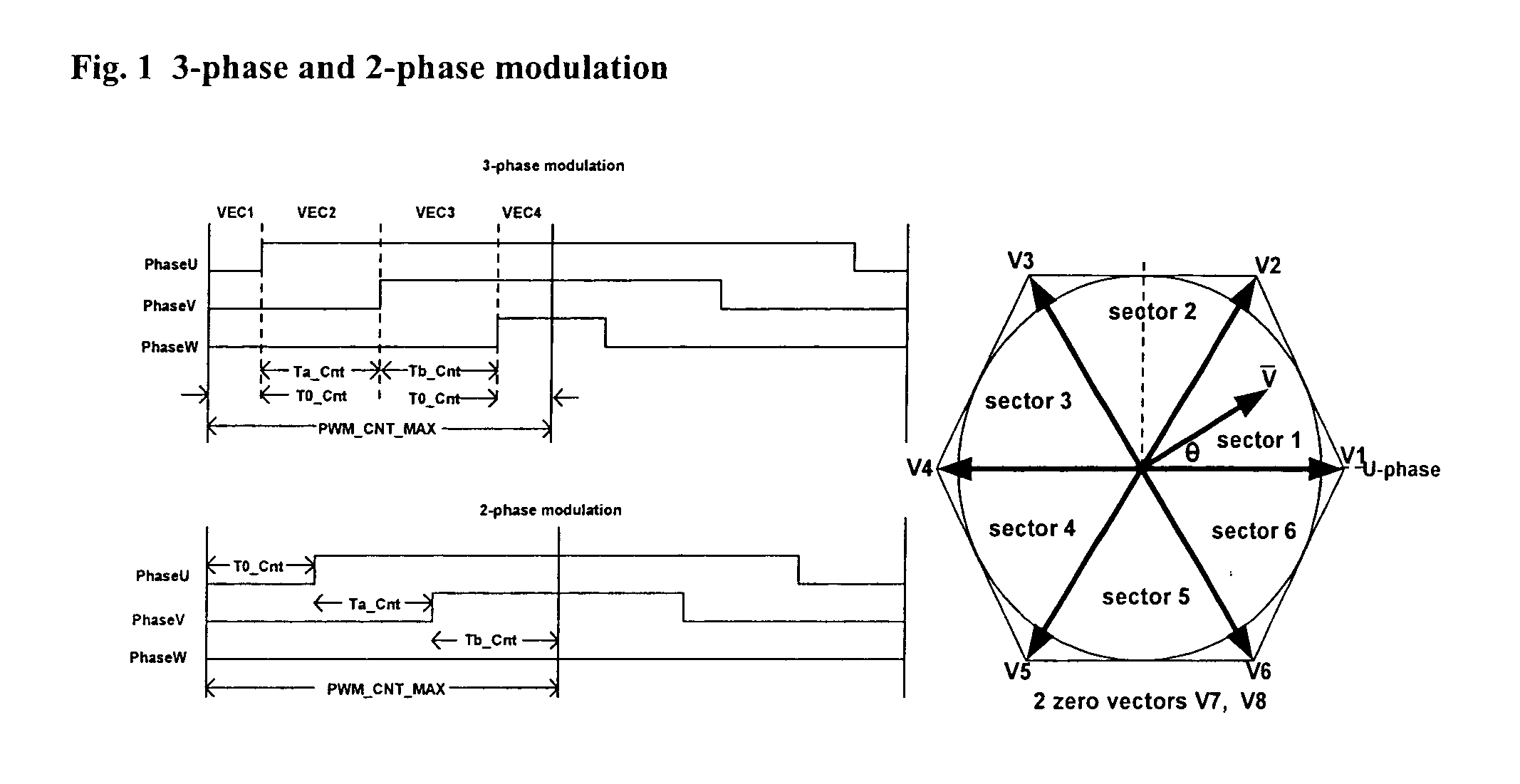
[0028] 3-phase and 2-phase PWM modulation schemes are shown in FIG. 1. The Volt-sec generated by the two PWM strategies are identical. However, with 2-phase modulation, the switching losses can be reduced significantly, especially when high switching frequency (>10 kHz) is employed.

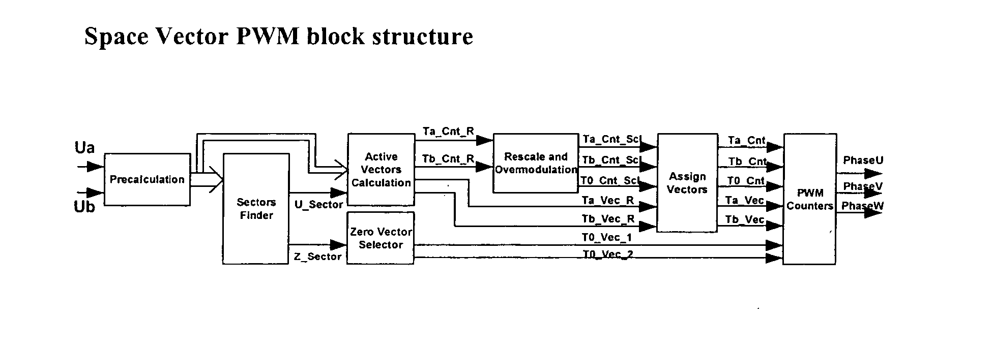
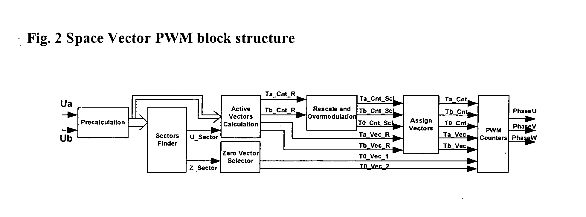
[0029] FIG. 2 shows the structural block diagram of the Versatile Space Vector PWM modulator. The design of each block will be described below in more detail. The features of this SVPWM are:

[0030] Implementation does not require Arctan, Sine, Cosine or Square root functions

[0031] Accepts rectangular inputs Ua and Ub (can easily interface to most Vector Controllers)

[0032] Zero vectors can be selected as desired

[0033] Simple overmodulation scheme by zero vector time clamping

[0034] Automatic Symmetrical and Asymmetrical mode generation by half PWM cycle updating.

[0035] FIG. 3 shows details of the calculations in the Precalculation and Sector F...


PUM


Abstract

A space vector pulse-width modulator (SVPWM) and a method implemented by the modulator. A precalculation module accepts Ua and Ub modulation indexes and in response thereto, outputs modified Ua and Ub information; a sector finder has a U module which receives the modified Ua information and outputs a U sector; and a Z module which receives the U sector and the modified Ub information and outputs a Z sector. The U sector and the Z sector are 2-phase control signals for implementing 2-phase modulation. For 3-phase modulation, the SVPWM and method further possess an active vectors calculation module and an assign vectors module which receive the modified Ua and Ub information and the U sector, and which calculate active vectors for 3-phase modulation; a zero vector selector which receives the Z sector and calculates zero vectors for 3-phase modulation; and a PWM counter block which receives the active vectors and zero vectors and outputs 3-phase control signals for implementing 3-phase modulation. The SVPWM and method may have a symmetrical PWM mode, an asymmetrical PWM mode, or both. Advantageously there may also be a rescale and overmodulation module which receives duration information corresponding to the vectors and in response thereto, detects the occurrence of overmodulation. Overmodulation may be detected in response to a negative zero vector time. The module may respond to overmodulation by clamping the zero vector time to zero and rescaling the active vector times to fit within the PWM cycle. The rescaling may restrict a voltage vector to stay within hexagonal boundaries on the space vector plane, while preserving voltage phase.

Description

CROSS-REFERENCE[0001] This application is based on and claims priority of U.S. Provisional Application Serial No. 60 / 418,733 filed Oct. 15, 2002, incorporated by reference.[0002] 1. Field of the Invention[0003] The invention relates to a motor drive, and more particularly to a drive method and system for a permanent magnet surface-mount (PMSM) motor utilizing a space-vector PWM modulation scheme.[0004] 2. Description of the Related Art[0005] Three-phase motor drives utilizing inverters are well known in the industry. Typically a DC bus supplies switched power to different phases of an AC motor. For supplying switching commands and sequences to the inverter, sensorless vector control is achieving wide attention. Sensorless control eliminates speed, flux and torque sensors and replaces them with DSP-based estimation based on the measured terminal voltages and currents. Thus, the cost of the drive is reduced and reliability is enhanced. A DSP-based motor drive of background interest is...

Claims


Application Information

Patent Timeline
Patent Type & Authority Applications(United States)
IPC IPC(8): H02M7/5387H02P21/00
CPCH02P21/0035H02M7/53873H02P21/22H02M7/527H03K7/08H02M7/48
Inventor HO, EDDY YING YIN
Owner INFINEON TECH AMERICAS CORP
Learn More