

Air bag apparatus
a technology of airbags and airbags, which is applied in the direction of vehicular safety arrangements, vehicle components, pedestrian/occupant safety arrangements, etc., can solve the problems of inability to achieve satisfactory holding performance for passengers, difficulty in finely adjusting the maximum pressure in a stepless manner, and limit the maximum output adjustmen
- Summary
- Abstract
- Description
- Claims
- Application Information
AI Technical Summary
Benefits of technology
Problems solved by technology
Method used
Image

Examples
embodiment 1
1 Embodiment 1
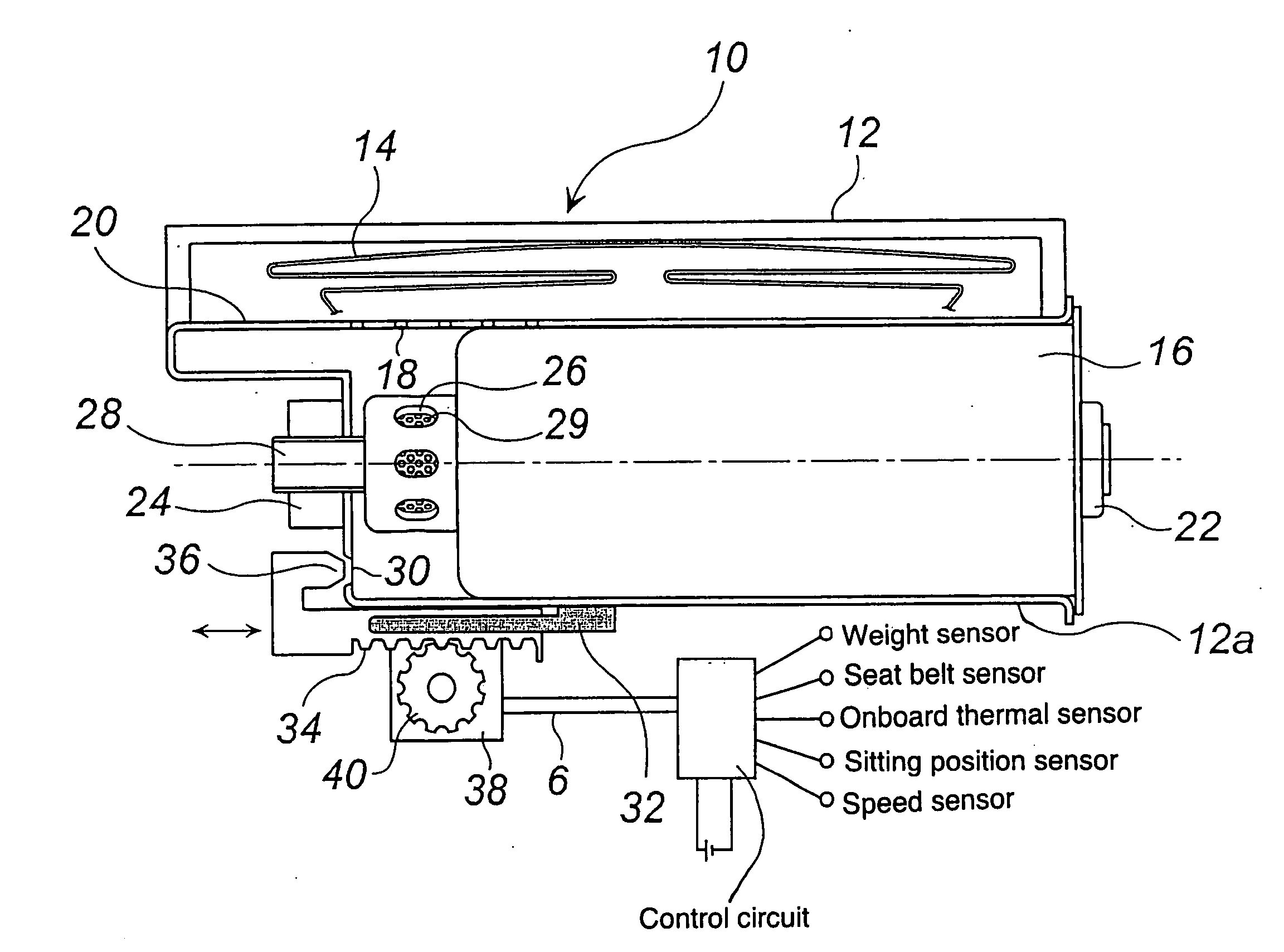
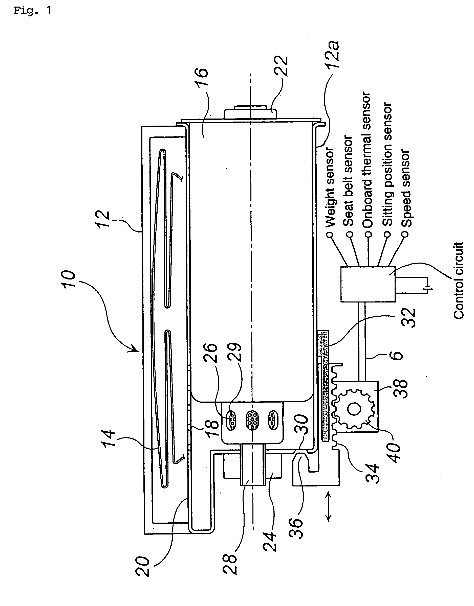
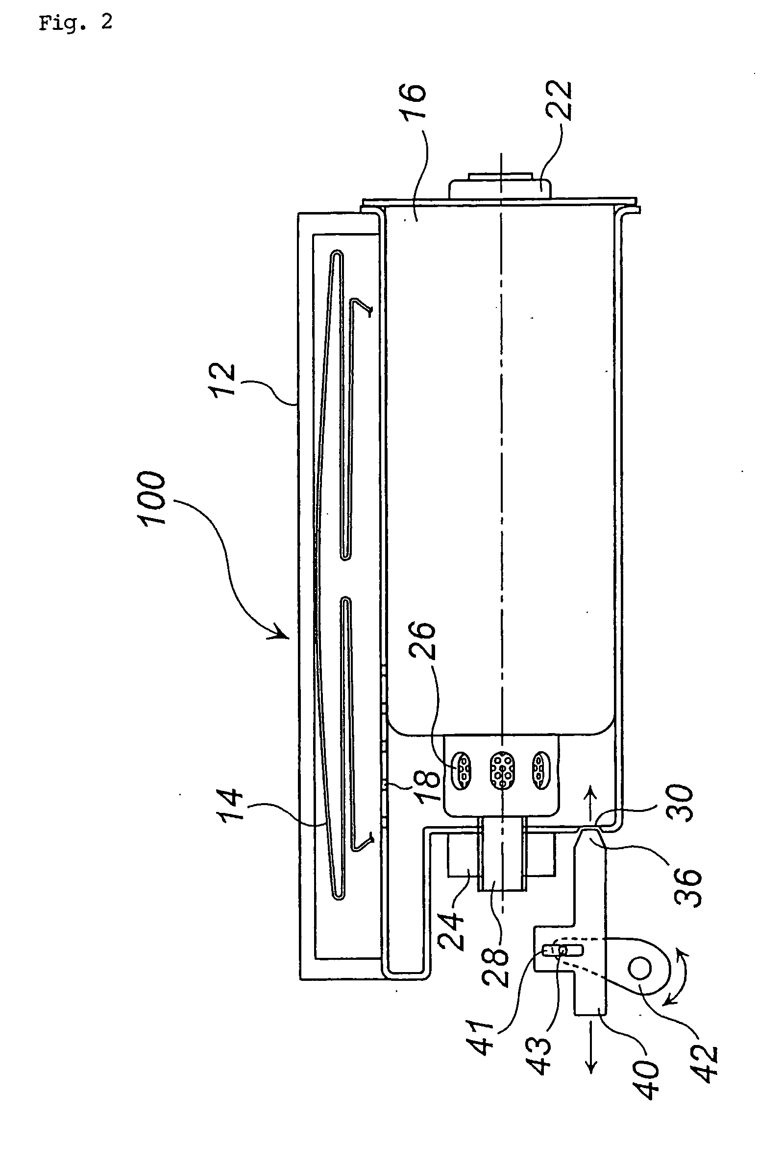
[0049] FIG. 1 is a schematic sectional view of an air bag apparatus 10, FIG. 2 is a schematic sectional view of an air bag apparatus 100 of the same embodiment except that the apparatuses 10 and 100 are different in stepless adjusting mechanism, and FIG. 3 is a conceptual view for explaining a state of an air bag apparatus mounted to a vehicle, in which a control circuit is omitted.
[0050] As shown in FIG. 1 and FIG. 2, an air bag 14 and an inflator 16 are accommodated in the interior of a module case 12, and a partition wall 20 having gas inflow ports 18 closes between the air bag 14 and the inflator 16. The inflator 16 is fixed, at the axial both ends, to two surfaces of the module case 12 by a bolt 22 and a nut 24.
[0051] The inflator 16 has a required number of gas discharging ports 16 and a stud bolt 28 (screwed with the nut 24) integrated with the inflator 16. Reference numeral 29 denotes a filter disposed inside the gas discharging ports 26 to remove foreign mater...
embodiment 2
2 Embodiment 2
[0086] An air bag apparatus will be explained with reference to FIG. 4. Since an air bag apparatus 200 shown in FIG. 4 and the air bag apparatus 10 shown in FIG. 1 are different only in a stepless adjusting mechanism, the other constitution elements of the air bag apparatus 200 are denoted by the same reference numerals as FIG. 1 and an explanation thereof will be omitted.
[0087] A movable coolant means 50 covering a gas discharging port 26 of an inflator 16 from the outside is disposed on the inflator 16 side inside the module case 12.
[0088] This movable coolant means 50 comprises a cylindrical coolant 51 and a clamp 52 supporting the coolant 51. The coolant 51 comprises a wire mesh, a punching metal, or a laminated body thereof, and it functions to cool a gas temperature without disturbing discharge of the gas.
[0089] The coolant 51 reciprocates straight in the axial direction of the inflator 16, interlocked with mesh between a rack 34 formed integrally with the clamp ...
embodiment 3
3 Embodiment 3
[0095] An air bag apparatus 300 will be explained with reference to FIG. 5. Since an air bag apparatus 300 shown in FIG. 5 and the air bag apparatus 10 shown in FIG. 1 are different only in a stepless adjusting mechanism, the other constitution elements are attached with the same reference numerals as those in FIG. 1 and explanation thereof will be omitted.
[0096] A movable cap 60 covering gas discharging port 26 of an inflator 16 from the outside is disposed in the inflator 16 side inside the module case 12. Here, a depth L1 of a concave portion of the movable cap 60 and a length L2 from a distal end surface of a diffuser portion 27 to a lower end portion of the gas discharging port 26 are in the relationship of L1
PUM
 Abstract
Description
Claims
Application Information