Turbojet electromechanical thrust reverser with servo-controlled door displacement

a technology of electromechanical thrust reverser and servo control, which is applied in the direction of engine control, machines/engines, aircraft power plants, etc., can solve the problems of large damage to the reverser and the turbojet, large difference in position between, and risk of reverser being distorted and thus damaged, so as to achieve the effect of reducing such drawbacks

Active Publication Date: 2004-07-22
SAFRAN ELECTRICAL & POWER
View PDF8 Cites 21 Cited by
  • Summary
  • Abstract
  • Description
  • Claims
  • Application Information

AI Technical Summary

Benefits of technology

0007] The present invention thus seeks to mitigate such drawbacks by proposing a compact electromechanical thrust reverser which makes it possible to detect and remedy both

Problems solved by technology

Non-synchronized displacement of the doors generates high levels of dynamic stress on the reverser and can cause large amounts of damage to the reverser and the turbojet.
Poor synchronization of door displacement results from different loadings on the doors, leading to a large difference in position between them.
Under such circumstances, risks can arise of the reverser being distorted and thus damaged.
Thrust reverser technology using a hydraulic control system presents drawbacks associated in particular with the volume occupied by the various hyd

Method used


Image

  • Turbojet electromechanical thrust reverser with servo-controlled door displacement
  • Turbojet electromechanical thrust reverser with servo-controlled door displacement
  • Turbojet electromechanical thrust reverser with servo-controlled door displacement

Examples


Embodiment Construction

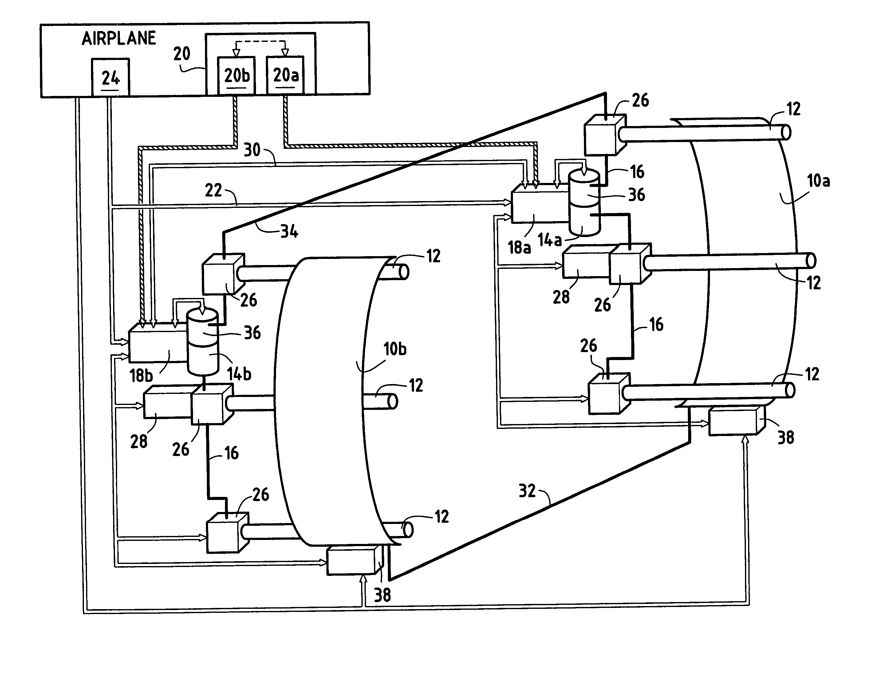
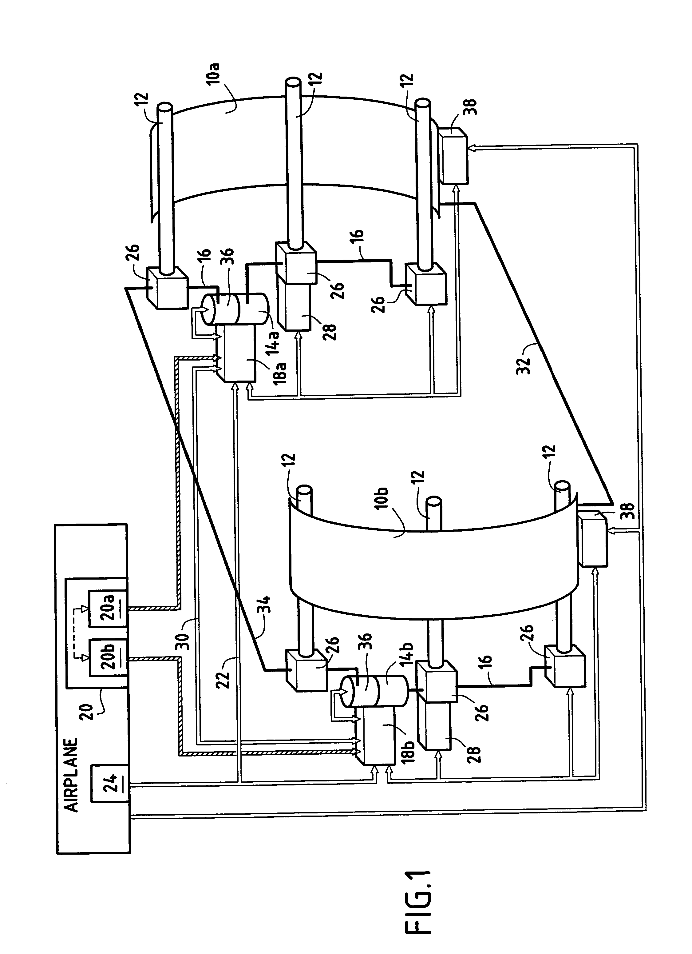
[0016] Reference is made initially to FIG. 1 which shows an embodiment of a thrust reverser of the invention.

[0017] The thrust reverser has two doors 10a, 10b each displaceable between an open position and a closed position of the reverser by means of least one control actuator 12 (three actuators are shown in FIG. 1, a central actuator and two actuators positioned at two lateral extremities of each door).

[0018] The reverser further includes two electric motors 14a and 14b each controlling the displacement of a respective door. These electric motors drive the control actuators 12 of each of the doors 10a, 10b via transmission shafts 16 interconnecting the control actuators of each door.

[0019] Each electric motor 14a, 14b is mounted directly on an electronic control unit 18a, 18b which manages the entire displacement sequence of the two doors and regulates the speed of rotation of the electric motor. Each electronic control unit 18a, 18b is electrically connected to one of the two ch...


PUM


Abstract

A turbojet thrust reverser comprising two doors each displaceable between an open position and a closed position of the reverser by means of at least one respective control actuator; two electric motors each driving said at least one control actuator for each door; each motor being controlled by an electronic control unit connected to a full authority digital engine control; and two servo-control means for controlling the displacement of corresponding ones of said doors as a function of determined position references, said servo-control means enabling said doors to be displaced synchronously as a function of any variation in the forces exerted on the reverser and as a function of any force difference between the two doors.

Description

[0001] The present invention relates to the general field of thrust reversers for bypass turbojets. It relates more particularly to an electromechanical thrust reverser having at least two displaceable elements which co-operate, when the reverser is in its open position, in producing thrust reversal, such as, for example, a thrust reverser having doors, grids, or shells.[0002] Thrust reversers fitted to bypass turbojets are well known in the field of aviation. They serve to increase aircraft safety by assisting in braking during landing. Thrust reversers are generally in the form of at least two moving elements, such as sliding doors, which are suitable for being moved relative to the pod of the turbojet by control actuators so that when operating in thrust reversal, i.e. when in the open position, they constitute an obstacle for a fraction of the gas coming from the turbojet, which fraction is diverted forwards so as to deliver reverse thrust to the airplane.[0003] The sliding door...

Claims


Application Information

Patent Timeline
IPC IPC(8): F02K1/32B64D33/00F02K1/54F02K1/70F02K1/76
CPCF02K1/763F05D2270/62F05D2270/54
Inventor COLOTTE, BAPTISTECOURPIED, ALEXANDRECROIXMARIE, MARCJOLAND, PATRICKLE GOUELLEC, GILLESMICHAU, MARION
Owner SAFRAN ELECTRICAL & POWER
Why Eureka
Try Eureka