Method of controlling pulsation resonance point generating area in opposed engine or in-line engine

a technology of pulsation resonance and opposed engines, which is applied in the direction of liquid fuel feeders, machines/engines, mechanical apparatus, etc., can solve the problems of low propagation rate of pulsation wave in the fuel delivery pipe, increase the temperature of the fuel tank, and increase the temperature of the gasoline, so as to reduce the rigidity of the fuel delivery pipe and improve the absorption ability of the pulsation wave. , the effect of characterizing the period

Inactive Publication Date: 2004-07-29
USUI KOKUSAI SANGYO KAISHA LTD
View PDF3 Cites 4 Cited by
  • Summary
  • Abstract
  • Description
  • Claims
  • Application Information

AI Technical Summary

Benefits of technology

0066] As shown in FIG. 21, the characteristic period of the pulsation wave in the in-line type engine is approximately inversely proportioned to the propagation speed of the pulsation wave in the fuel delivery pipe. That is, the characteristic period of the pulsation wave can be made longer by lowering the rigidity of the fuel delivery pipe to raise the absorption ability of the pulsation wave and to reduce the propagation speed of the pulsation wave, and as a result, the pulsation resonance period can be made longer. The propagation speed of the pulsation wave in the supplying pipe has almost no effect in the characteristic period of the pulsation wave in the in-line engine as shown in FIG. 22. The characteristic period of the pulsation wave in the in-line type engine is substantially proportioned to the square root of the length of the fuel delivery pipe as shown in FIG. 23 and is also proportioned to the square root of the supplying pipe as shown in FIG. 24. Therefore, the characteristic period of the pulsation wave can be made longer by extending the length of the fuel delivery pipe or extending the length of the supplying pipe, and as a result, the pulsation resonance period can be made longer.
0067] The characteristic period of the pulsation wave in the in-line type engine is inversely proporti...

Problems solved by technology

However, the fuel supplied to the fuel delivery pipe disposed adjacently to the engine cylinder heated at a high temperature increases the temperature of the fuel, and the gasoline temperature in the fuel tank may be increased by returning the excessive fuel of the high temperature to the fuel tank.
With this increased temperature, the gasoline may be gassed and unfavorably affect the environments adversely, so that the non-return type fuel delivery pipes have been proposed in which the excessive fuel is not returned to the fuel tank.
In a case where the fuel delivery pipe itself has a mechanism absorbing the pulsation wave with elastic transformation thereof, the propagation rate of the pulsation wave in the fuel delivery pipe becomes low due to significant differences in the elasticity thereof.
This makes the mixing rate of the fuel gas and the air different from the designed value, so that the exhaustion gas may be adversely affected, or that the designed power may not be pulled out.
The pulsation resonance induces mechanical vibrations at the supplying pipe coupled to the side of the fuel tank, and is propagated as noises in the pa...

Method used


Image

  • Method of controlling pulsation resonance point generating area in opposed engine or in-line engine
  • Method of controlling pulsation resonance point generating area in opposed engine or in-line engine
  • Method of controlling pulsation resonance point generating area in opposed engine or in-line engine

Examples


Embodiment Construction

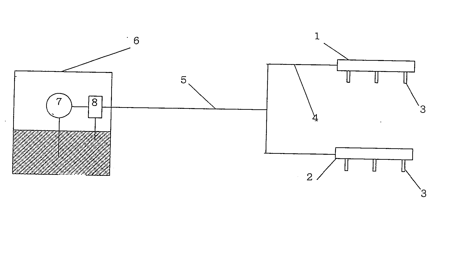
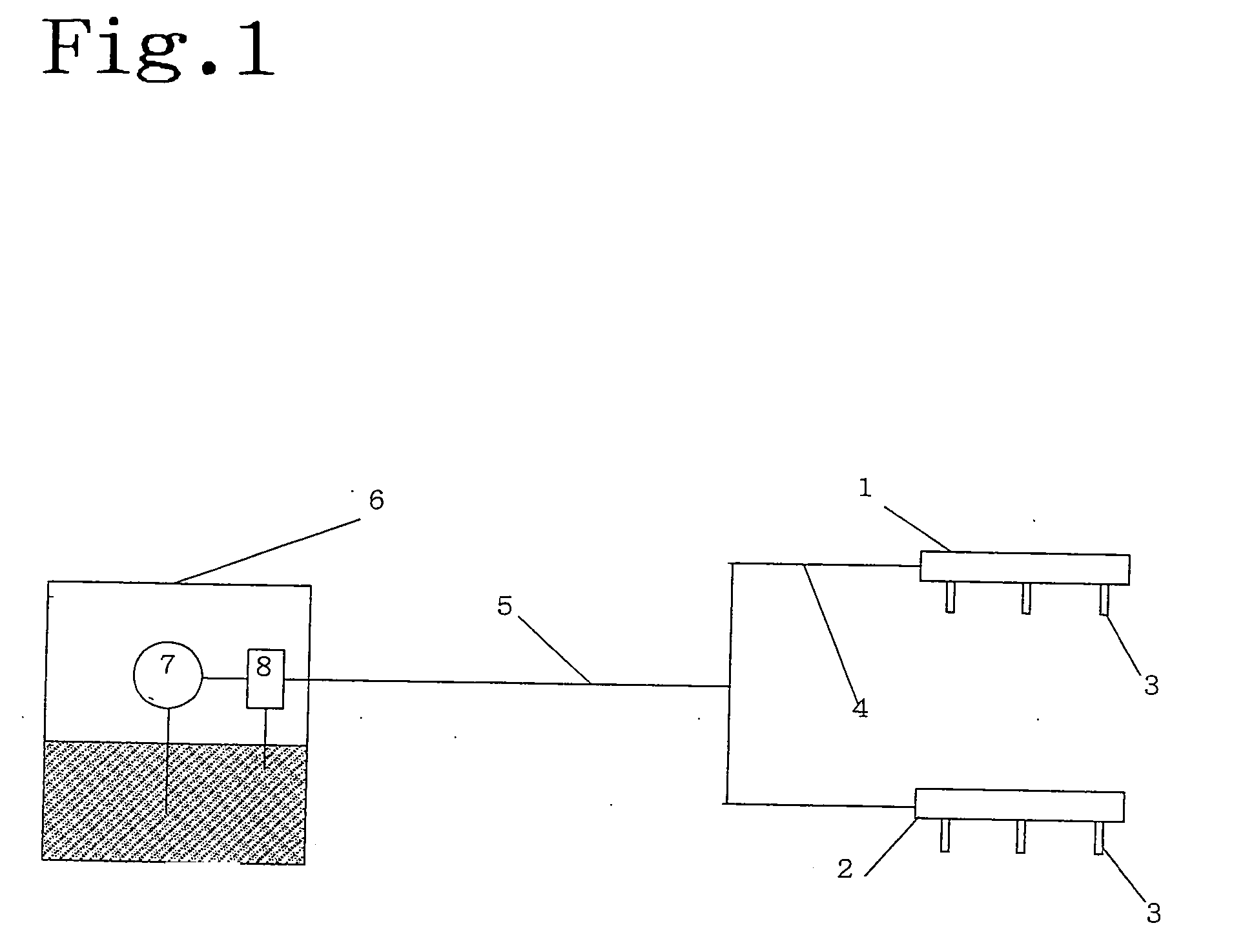
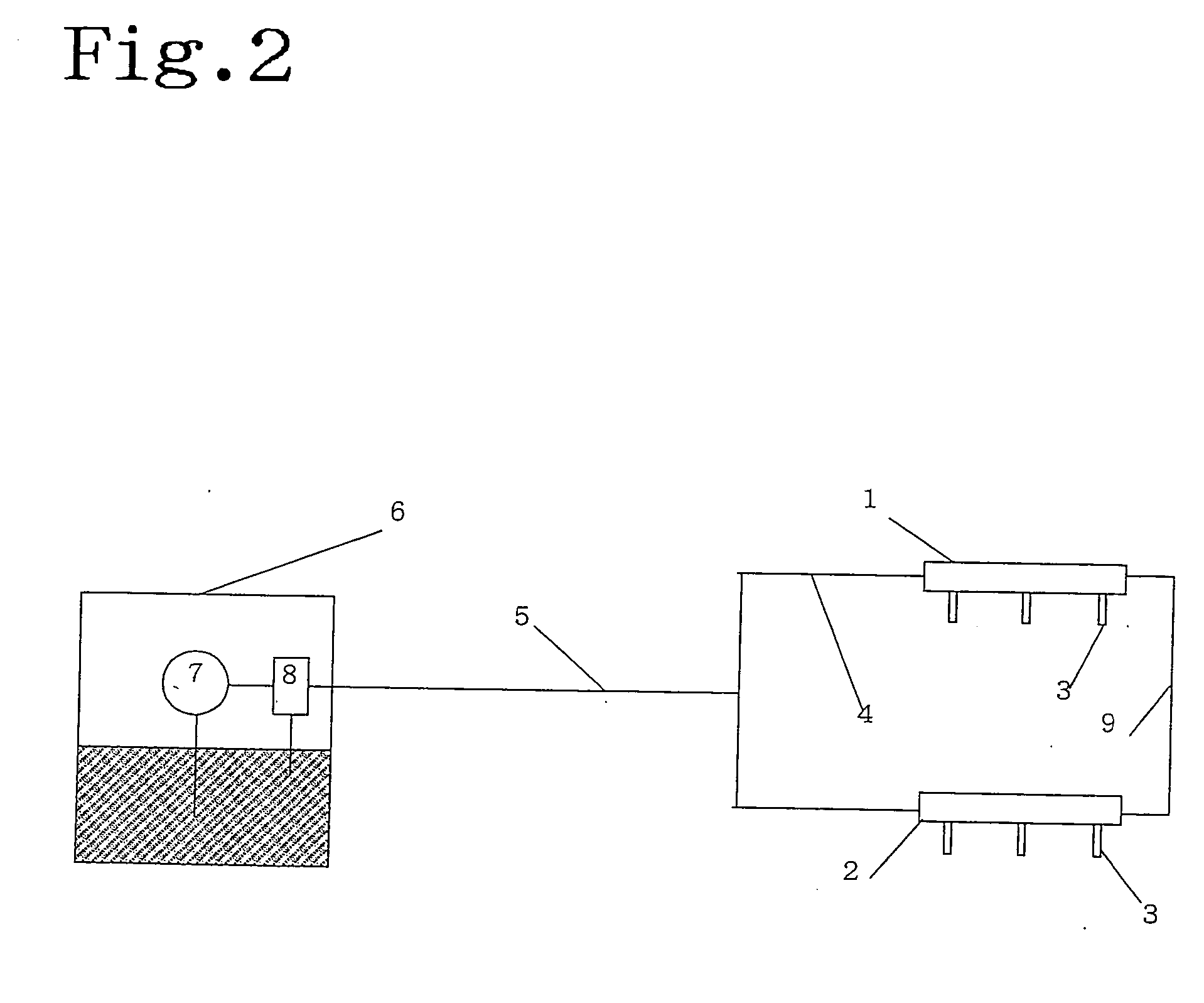
[0069] Embodiments of the invention are described. Based on a structure at an experiment described with FIG. 15, a description is made. In an opposed type engine, as shown in FIG. 1, injection nozzles (3) are mounted three pieces for each pipe at a pair of fuel delivery pipes (1), (2). The length of the fuel delivery pipes (1), (2) were 315 mm in the experiment. In the experiment, the injection nozzles were opened on the injection side. The pair of the fuel delivery pipes (1), (2) were coupled with a connection pipe (4). The connection pipe (4) was in a cylindrical pipe having an outer diameter of 8 mm and a thickness of 0.7 mm, whose length was of four kinds, 210 mm, 700 mm, 2600 mm, and 3200 mm. An intermediate point of the connection pipe (4) was connected to a supplying pipe (5). The supplying pipe (5) was in a cylindrical pipe having an outer diameter of 8 mm, a thickness of 0.7 mm, in the same way as the connection pipe (4), and a length of 2000 mm. A tip of the supplying pipe...


PUM


Abstract

In a fuel supplying mechanism in which fuel delivery pipes of a non-return type are disposed, the generation region of pulsation resonance is arbitrarily controlled, thereby eliminating various disadvantages otherwise occurring where the pulsation resonance point exists in a favorable rotation region for normal use of the engine. A pair of the fuel delivery pipes 1, 2 of a non-return type is disposed for each bank of a horizontal opposed type or V-type engine and coupled with a connection pipe 4. A characteristic period time of a pulsation wave induced by the pulsation wave generated during fuel injection of the injection nozzles 3 via a connection pipe 4 coupling between one to the other of the fuel delivery pipes 1, 2 is controlled to render the characteristic period time longer to shift the pulsation resonance point out of a low rotation region of the engine as well as to render the characteristic period time shorter to shift the pulsation resonance point out of a high rotation region of the engine.

Description

[0001] This invention relates to a method controlling a pulsation resonance point generating region in opposed type engine or in-line type engine for transiting out of a desirable rotational rate zone of the normal use of the engine a generating point of pulsation resonance generated due to pulsation wave in the opposed type engine or in-line type engine such as a V-type engine, a horizontal opposed type engine, and the like.[0002] Fuel delivery pipes have conventionally been known in which fuel such as gasoline is supplied to plural cylinders of the engine upon providing plural injection nozzles. The fuel delivery pipe injects the fuel introduced from a fuel tank out of the plural injection nozzles to the inside of a plurality of intake pipes or cylinders of the engine, mixes the fuel wit the air, and generates the engine output by burning the mixture gas.[0003] The fuel delivery pipe, as described above, is for injecting the fuel supplied from the fuel tank via a supplying pipe ou...

Claims


Application Information

Patent Timeline
IPC IPC(8): F02M55/02F02M55/04
CPCF02M55/04F02M2200/315F02M69/465F02M55/02
Inventor SERIZAWA, YOSHIYUKITSUCHIYA, HIKARIOGATA, TETSUOMIZUNO, KAZUTERUUSUI, MASAYOSHITAKIKAWA, KAZUNORI
Owner USUI KOKUSAI SANGYO KAISHA LTD
Why Eureka
Try Eureka