Moving picture coding method and a moving picture decoding method

a coding method and a technology for moving pictures, applied in the field of moving picture coding methods and moving picture decoding methods, can solve the problems of degrading coding efficiency, reducing the processing burden caused by motion estimation, and inability to use bidirectional predictive pictures, so as to reduce the processing burden and effective coding

Active Publication Date: 2004-07-29
GK BRIDGE 1
View PDF7 Cites 42 Cited by
  • Summary
  • Abstract
  • Description
  • Claims
  • Application Information

AI Technical Summary

Benefits of technology

0025] The present invention is conceived in view of above circumstances, and aims to provide a moving picture coding method and a moving picture decoding method for realizing an effective coding as well as a reduction of the processing burden when a plural reference picture interpolation prediction is performed.

Problems solved by technology

However, an information compression technique for data is dispensable for its storage and transmission since a digitalized picture contains an enormous amount of data.
However, the arbitrary reference pictures are selected by performing motion estimation for the plurality of the coded pictures in this case, therefore, the processing burden caused by the motion estimation becomes very large.
The plural reference picture interpolation prediction also contains a problem of degrading the coding efficiency since it requires coding of reference picture numbers and motion vectors for every two reference pictures.
Furthermore, when inter-picture prediction is performed for a picture using a picture whose display time is later than that of the current picture as a reference picture, as in the case of bi-directional prediction described in the conventional technique, the picture has to be coded in an order different from a display order, which causes a delay.
In a case of real time communication such as a videophone, bidirectional predictive pictures cannot be used because of the delay.
However, the picture whose display time is later than that of the current picture is not stored in the multi-picture buffer, therefore, the direct mode conventionally used for determining the motion vectors using the picture whose display time is later than that of the current picture as described above cannot be employed.

Method used


Image

  • Moving picture coding method and a moving picture decoding method
  • Moving picture coding method and a moving picture decoding method
  • Moving picture coding method and a moving picture decoding method

Examples


first embodiment

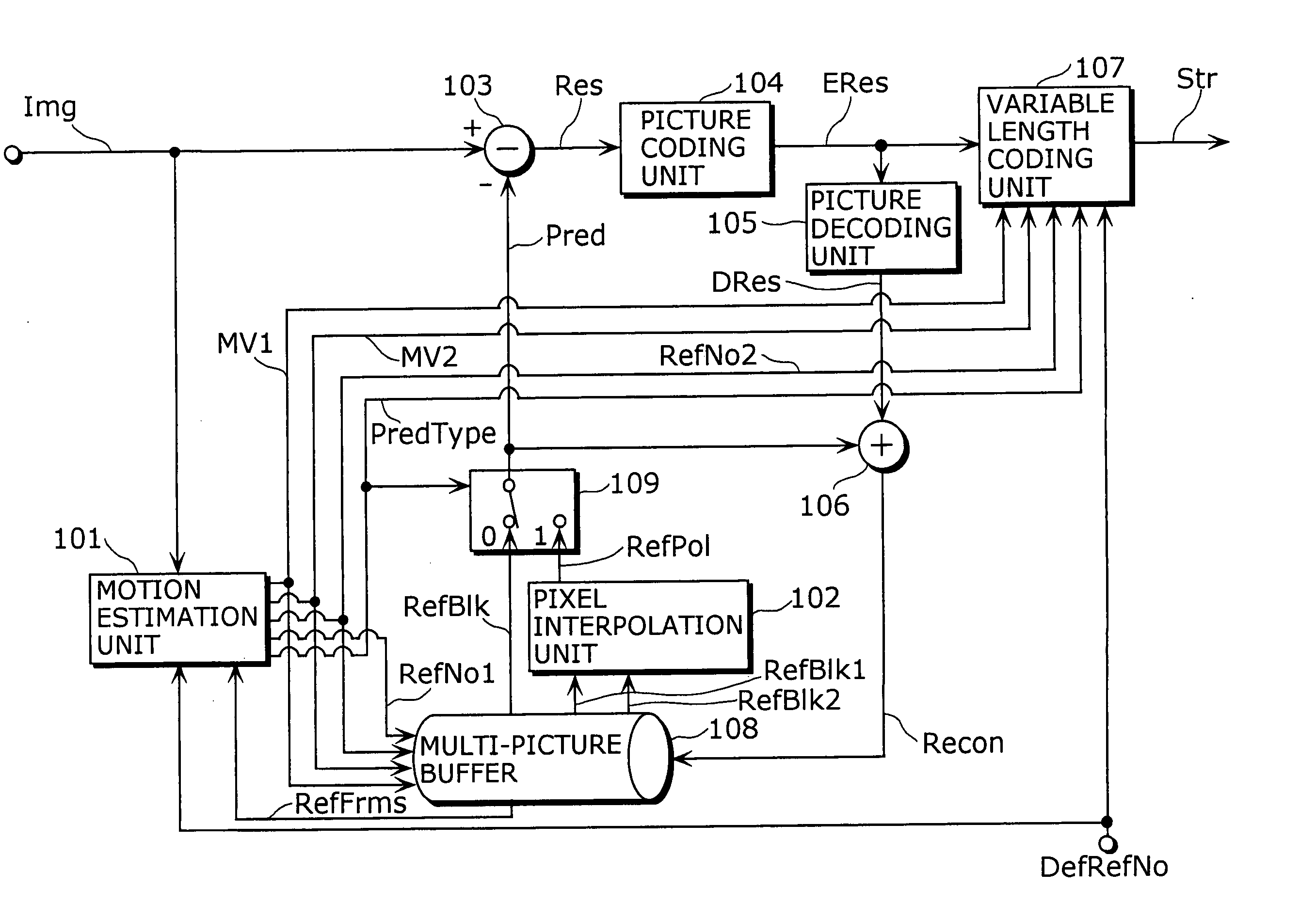
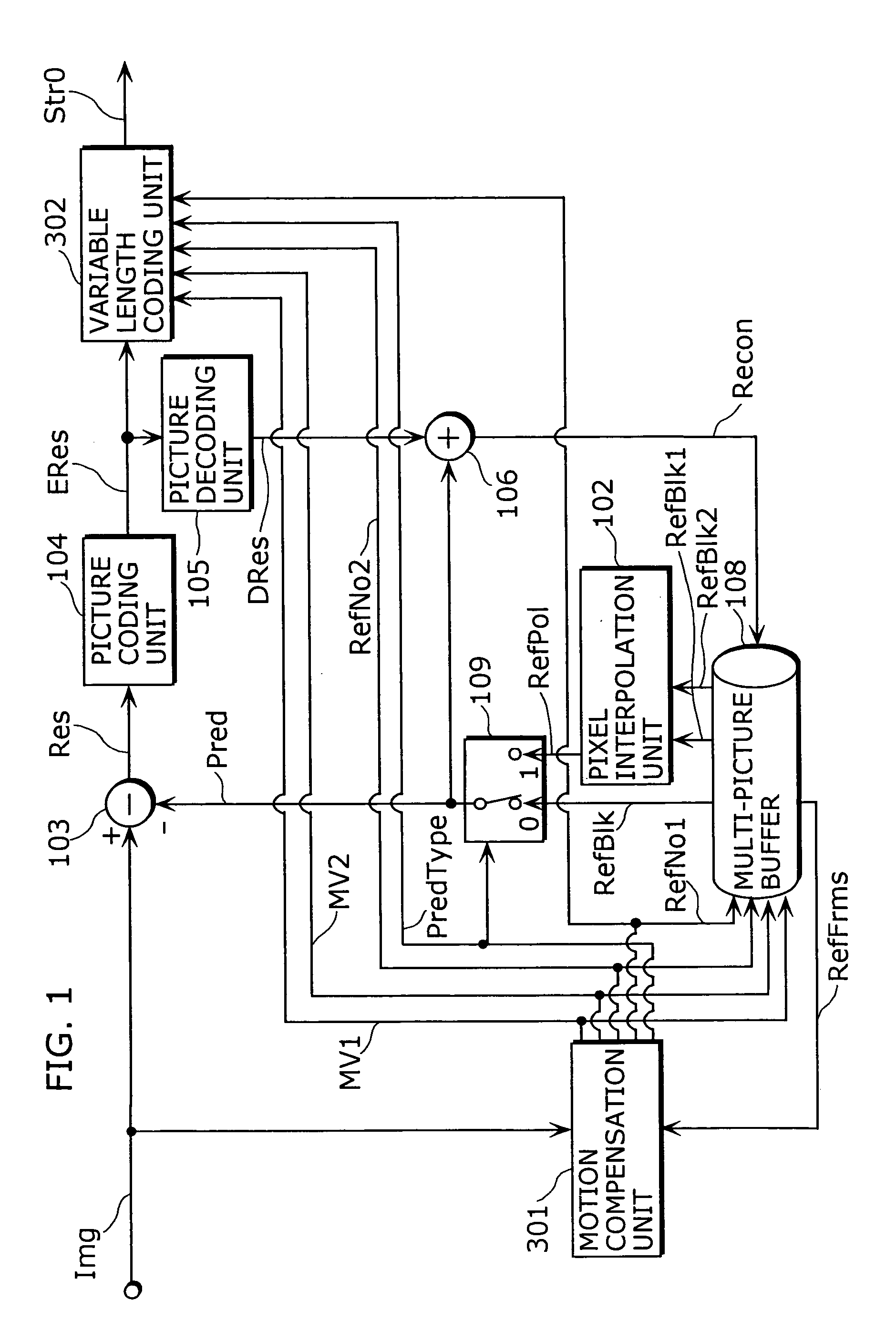
[0062] FIG. 6 is a block diagram showing a structure of a moving picture coding apparatus according to the The same marks are put for the units and the data operating in the same manner as described in the block diagram showing a structure of a conventional moving picture coding apparatus in FIG. 1 and the description will be abbreviated. It is possible for the moving picture coding apparatus and the moving picture decoding apparatus according to each embodiment described below to switch, on a block-by-block basis, between the following prediction methods: a method of generating a predictive image by pixel interpolation using two reference pictures (a plural reference picture interpolation prediction); a method of using a block included in a single arbitrary picture directly as a predictive image; a method of generating a predictive image using an intra-picture prediction.

[0063] The moving picture coding apparatus is an apparatus for dividing an inputted picture data Img into block...

second embodiment

[0079] FIG. 8 is a block diagram showing a moving picture decoding apparatus according to the second embodiment of the present invention. The same marks are put for the units and the data operating in the same manner as illustrated in the block diagram showing a structure of the conventional moving picture decoding apparatus in FIG. 4, and the description will be abbreviated. The difference between the moving picture decoding apparatus of the present embodiment and the conventional one shown in FIG. 4 is that a default reference picture number buffer 402 is added to the former.

[0080] The moving picture decoding apparatus, as shown in FIG. 8, includes a variable length decoding unit 401, a default reference picture number buffer 402, a motion compensation unit 403, a picture decoding unit 404, an adder 405, a pixel interpolation unit 406, a multi-picture buffer 407 and a switch 408.

[0081] The variable length decoding unit 401 performs variable length decoding on the inputted coded mo...

third embodiment

[0087] FIG. 9 is a block diagram showing a moving picture coding apparatus according to the third embodiment of the present invention. The same marks are put for the units and the data operating in the same manner as shown in the block diagram illustrating the moving picture coding apparatus according to the first embodiment in FIG. 6, and the description will be abbreviated.

[0088] The moving picture coding apparatus of the present embodiment includes a default reference picture number generation unit 201 in addition to the structure shown in the first embodiment. The default reference picture number generation unit 201 generates a default reference picture number DefRefNo using a predetermined method and outputs it to the motion estimation unit 101. The motion estimation unit 101 performs motion estimation, by fixing the one of two reference pictures as the reference picture indicated by the inputted default reference picture number DefRefNo, when the plural reference picture inter...


PUM


Abstract

A moving picture coding apparatus includes a motion estimation unit (101) for performing motion estimation by fixing the one of two reference pictures as a reference picture indicated by an inputted default reference picture number DefRefNo and a variable length coding unit (107) for performing variable length coding on coded residual data ERes, a prediction type PredType, a reference picture number RefNo2 and motion vectors MV1, MV2 on a block-by-block basis, and outputting them as coded moving picture data Str.

Description

[0001] The present invention relates to a method of coding and decoding moving picture data as well as a recording medium on which a program for executing these methods as software is recorded.[0002] In recent years, along with a development of multimedia applications such as picture, audio and text, it has become general to handle all sorts of media in an integrated way. However, an information compression technique for data is dispensable for its storage and transmission since a digitalized picture contains an enormous amount of data. On the other hand, a standardization of compression techniques is also important for interoperating compressed picture data. The standards of picture compression techniques include h.261, H.263 established by the ITU (International Telecommunication Union) and MPEG (Moving Picture Experts Group)-1, MPEG-2 and MPEG-4 established by the ISO (International Organization for Standardization).[0003] An inter-picture prediction which accompanies motion comp...

Claims


Application Information

Patent Timeline
Patent Type & Authority Applications(United States)
IPC IPC(8): H04N19/50G06T9/00H04N19/105H04N19/136H04N19/139H04N19/172H04N19/174H04N19/176H04N19/196H04N19/423H04N19/46H04N19/503H04N19/51H04N19/513H04N19/59H04N19/593H04N19/60H04N19/61H04N19/70H04N19/85H04N19/91
CPCH04N19/00H04N19/577H04N19/50H04N19/176H04N19/70H04N19/172H04N19/46H04N19/51H04N19/61H04N19/107H04N19/109H04N19/91H04N19/146H04N19/573H04N19/58H04N19/105H04N19/15H04N19/159H04N19/17H04N19/174H04N19/182H04N19/503
Inventor HAGAI, MAKOTOKADONO, SHINYAKONDO, SATOSHIABE, KIYOFUMI
Owner GK BRIDGE 1
Why Eureka
Try Eureka