Supercharge Your Innovation With Domain-Expert AI Agents!

Starting device for internal combustion engine

a technology of starting device and internal combustion engine, which is applied in the direction of engine starter, engine components, machines/engines, etc., can solve the problems of high reaction force, difficult to achieve design-related gap in the required quality in series production, and considerable force acting on the hand of the operator

Inactive Publication Date: 2004-08-05
DOLMAR
View PDF8 Cites 13 Cited by
  • Summary
  • Abstract
  • Description
  • Claims
  • Application Information

AI Technical Summary

Benefits of technology

[0018] comprises at least one bushing or sleeve, in particular a thin-walled bushing or sleeve, by means of which this gap can at least partly be filled. As a result of this, the elastic coupling element or a part thereof can simply, effectively and reliably be prevented from entering the design-related gap between the pulley or rope drum and the engaging element.
[0020] This proposal is as simple as it is reliable and effective, since the bushing or sleeve, which is preferably in the shape of a hollow cylinder, can be put over the two opposite shaft ends without any problem so that any deformation of the spring which is used is safely prevented.
[0022] As a result of this, the required operating gap (=design-related gap or design-related separation joint) between the axle of the pulley or rope drum and the axle of the (ratchet-type) engaging element no longer has any influence on the spring. As a result of this, the tolerances can be larger, which in turn makes it possible to produce the starting device more economically.

Problems solved by technology

In the past, the operation of a starting device for an internal combustion engine, in particular of a pull-rope type starting device for a two-stroke or four-stroke motor, has often caused problems because during the starting process the compression in the internal combustion engine periodically leads to high reaction forces occurring as a result of which changing and temporarily very considerable forces act on the hand of the operator.
(An earlier attempt to design the load transfer means so as to be elastic itself led to unsatisfactory results.)
This placement of the spiral spring against the shaft results in a blockage of any further rotation so that the engaging element of the crankshaft is forced to rotate with the pulley or rope drum.
However, in practical application, this design (=the light-start system supplied by Starting Industrial Co., Ltd., according to the so-called coil-spring principle) has been associated with disadvantages in that there is a design-related gap between the pulley or rope drum and the engaging element, with said design-related gap being defined by the longitudinal tolerance of three components, and with said design-related gap being difficult to achieve in the required quality in series production.
In conclusion, this means that when a specific tolerance dimension is exceeded, at least part of a coil of the spiral spring enters the gap between the pulley or rope drum and the engaging element which are connected by the spiral spring, thus naturally becoming overstretched and sustaining permanent deformation.
As a result of this, the system ceases to function properly and blocks.
In extreme cases this can result in the spiral spring breaking so that the starting device ceases to function and the internal combustion engine can no longer be started at all.
It is also possible for fragments of the broken spiral spring to damage adjacent components of the starting device.

Method used


Image

  • Starting device for internal combustion engine
  • Starting device for internal combustion engine
  • Starting device for internal combustion engine

Examples


first embodiment

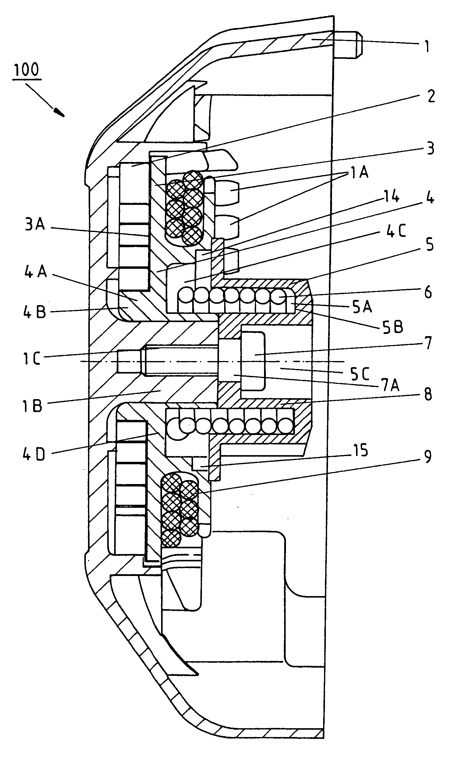
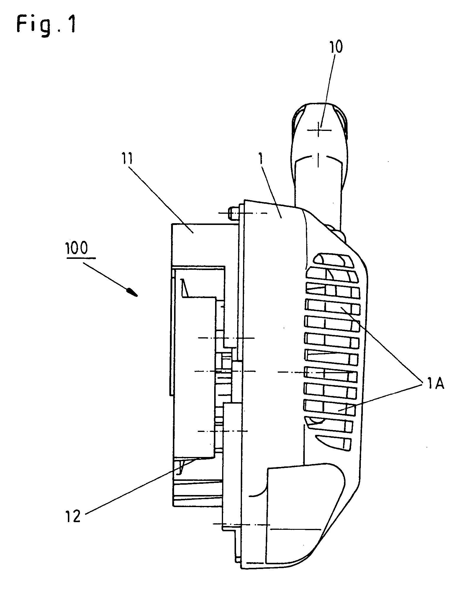
[0068] When this maximum angle of rotation in the magnitude of approximately 270 degrees to approximately 280 degrees has been reached, the spiral spring 6 places itself against the shaft, due to becoming smaller as a result of rotation. In the first embodiment according to FIGS. 1 to 5B, this placement of the spiral spring 6 against the shaft results in a blockage of any further rotation so that the ratchet-type engaging element 5 of the crankshaft is forced to rotate with the pulley or rope drum 4.

[0069] Consequently, the maximum load of the elastic coupling element 6 can be specified in a simple and yet effective and reliable way. As shown in FIGS. 5A and 5B, in the first embodiment this is achieved by providing a limit stop 13 by means of which the angle of rotation of the ratchet-type engaging element 5 is limited in relation to the pulley or rope drum 4 in order to prevent, in this way, any overloading of the elastic coupling element 6 during tensioning onto the block.

[0070] A...

second embodiment

[0074] When this maximum angle of rotation in the magnitude of approximately 135 degrees to approximately 140 degrees has been reached, the spiral spring 6 places itself against the shaft, due to becoming smaller as a result of rotation. In the second embodiment according to FIGS. 1, 2, 3, 6A, 6B, 7A, 7B, this placement of the spiral spring 6 against the shaft results in a blockage of any further rotation so that the ratchet-type engaging element 5 of the crankshaft is forced to rotate with the pulley or rope drum 4.

[0075] Consequently, the maximum load of the elastic coupling element 6 can be specified in a simple and yet effective and reliable way. As shown in FIGS. 7A and 7B, in the second embodiment this is achieved by providing two limit stops 13, 13' by means of which the angle of rotation of the ratchet-type engaging element 5 is limited in relation to the pulley or rope drum 4 in order to prevent, in this way, any overloading of the elastic coupling element 6 during tensioni...


PUM


Abstract

In order to improve a starting device (100) for at least one internal combustion engine, in particular a pull-rope type starting device for at least one two-stroke or four-stroke motor, which comprises at least one pulley or rope drum (4) which is rotatably held in at least one housing (1), wherein said starting device, for generating the drive torque for the motor shaft by means of at least one handle (10), in particular by means of at least one starter handle or pull handle, is rotatable by way of at least one load transfer means (9), in particular by way of at least one starter rope or pull-rope, and by way of at least one elastic coupling element (6), in particular by way of at least one spiral spring, is connected to at least one engaging element (5), in particular to at least one ratchet-type engaging element, by means of which the drive torque can be transmitted to the motor shaft, such that the elastic coupling element (6) or a part thereof can simply, effectively and reliably be prevented from entering the design-related gap between the pulley or rope drum (4) and the engaging element (5), it is proposed that at least one bushing or sleeve (8), in particular a thin-walled bushing or sleeve (8), be provided in this gap, by means of which bushing or sleeve (8) said gap can at least partly be filled.

Description

[0001] The present invention relates to a starting device for at least one internal combustion engine, in particular a pull-rope type starting device for at least one two-stroke or four-stroke motor, which comprises at least one pulley or rope drum which is rotatably held in at least one housing, wherein said starting device, for generating the drive torque for the motor shaft by means of at least one handle, in particular by means of at least one starter handle or pull handle, is rotatable by way of at least one load transfer means, in particular by way of at least one starter rope or pull-rope, and by way of at least one elastic coupling element, in particular by way of at least one spiral spring, is connected to at least one engaging element, in particular to at least one ratchet-type engaging element, by means of which the drive torque can be transmitted to the motor shaft.STATE OF THE ART[0002] In the past, the operation of a starting device for an internal combustion engine, i...

Claims


Application Information

Patent Timeline
Patent Type & Authority Applications(United States)
IPC IPC(8): F02N3/02
CPCF02N3/02F02N5/02
Inventor KRUSE, OLAFKRAHN, KLEMENS
Owner DOLMAR
Features
  • R&D
  • Intellectual Property
  • Life Sciences
  • Materials
  • Tech Scout
  • Unparalleled Data Quality
  • Higher Quality Content
  • 60% Fewer Hallucinations
Learn More