Eureka AIR delivers breakthrough ideas for toughest innovation challenges, trusted by R&D personnel around the world.

Milk measurement and milk collection

Inactive Publication Date: 2004-08-12
DELAVAL HLDG AB
View PDF2 Cites 17 Cited by
  • Summary
  • Abstract
  • Description
  • Claims
  • Application Information

AI Technical Summary

Benefits of technology

[0010] It is a further object to provide such method and device, which are reliable, of low cost, and easy to implement in an existing computer-controlled milking facility.
[0013] It is still a further object to provide such method and device, which are reliable, of low cost, and easy to implement in an existing dairy plant.
[0014] It is yet a further object to provide a computer program product loadable into a computer of the dairy plant for performing the above said method capable of planning an optimal milk collection route when said program product is run on said computer.
[0016] By the provision of a calibration / verification operation at the milking facility based on measurements performed by the dairy plant., or a laboratory contracted by it, the dairy plant will have an increased confidence in measurements performed by the milking facility. In some circumstances, the dairy plant needs thus only to perform random inspections of the measurements performed by the milking facility and in other circumstances the dairy plant can fully rely on the milking facility measurements.

Problems solved by technology

However, such milk measuring equipment nevertheless has to be of low cost such that the milk producers will invest in such equipment.
One drawback of such approach, however, is that such on-site measuring equipment may not provide accurate, precise and reliable measurements, and thus, such measurements may not be valuable to the milk producer.

Method used


Image

  • Milk measurement and milk collection
  • Milk measurement and milk collection
  • Milk measurement and milk collection

Examples


Embodiment Construction

[0024] In the following description, for purposes of explanation and not limitation, specific details are set forth, such as particular techniques and applications in order to provide a thorough understanding of the present invention. However, it will be apparent to one skilled in the art that the present invention may be practiced in other embodiments that depart from these specific details.

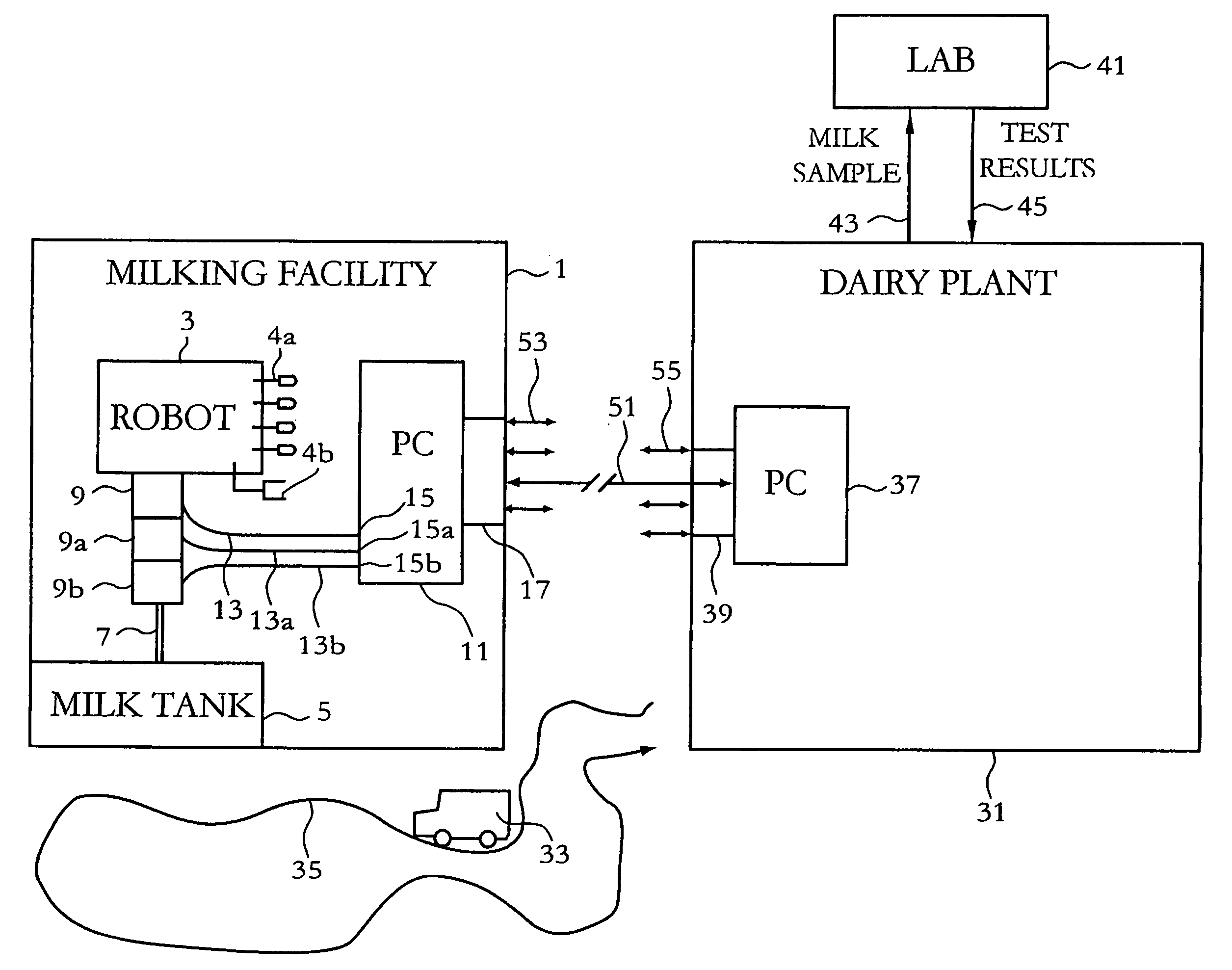
[0025] With reference to FIG. 1, which illustrates in a schematic view an automatic milking facility 1 and a dairy plant 31, respectively, which are connected by means of a bi-directional communication line 51, the present invention will be described.

[0026] The automatic milking facility 1 comprises an automatic milking robot 3 arranged for voluntary milking of freely walking cows, i.e. the cows enter the milking facility in order to be milked when they need to (or want to). The milking robot 3 includes four teat cups, schematically indicated at 4a, each being individually connectable to a sourc...


PUM


Abstract

In a milking facility (1) provided with on-site measuring equipment (9) capable of measuring a quality and / or quantity of milk produced, wherein the milk produced is stored in a milk tank (5) and is then collected (79) by a dairy plant, there is provided a method comprising the steps of: (i) receiving (61) a measured value indicative of the quality and / or quantity of milk produced in the milking facility from the on-site measuring equipment; (ii) receiving (99) from the dairy plant a corresponding measured value indicative of the quality and / or quantity of milk collected and transported, wherein the dairy plant is provided with high-quality measuring equipment (41); (iii) comparing (93) the measured values from the on-site measuring equipment of the milking facility and from the dairy plant; and (iv) calibrating or verifying (95) the on-site measuring equipment of the milking facility depending on the result of the comparison.

Description

[0001] The present invention generally relates to dairy farming and dairy industry.[0002] Particularly, the invention relates to a method and a device, respectively, in a computer-controlled milking facility aiming at improving milk measurements as performed at the milking facility, to a method and a device, respectively, in a dairy plant aiming at improving collection of milk from the milking facility as performed by the dairy plant, and to computer program products loadable into computers of the milking facility and the dairy plant, respectively, for performing the respective methods.DESCRIPTION OF RELATED ART AND BACKGROUND OF THE INVENTION[0003] In modern dairy farm industry there are continuous research and development activities in order to improve the efficiency of various activities such as machine milking, which, inter alia, involves increased milk yield and reduced milking time.[0004] A major trend in this respect is an increased degree of automation of the various activit...

Claims


Application Information

Patent Timeline
IPC IPC(8): A01J5/007A01J5/01G01N1/10G01N33/04
CPCA01J5/007G01N33/04G01N1/10A01J5/01
Inventor ERIKSSON
Owner DELAVAL HLDG AB
Why Eureka
Eureka Blog
Learn More