
Method of diagnosing a fault on a transformer winding

a transformer winding and fault technology, applied in the direction of electronic circuit testing, measurement devices, instruments, etc., can solve the problems of extremely expensive power transformers, short circuits that can run the risk of explosion or fire, and faults that cannot be detected, so as to increase the number of faults

Active Publication Date: 2004-08-26
ALSTOM TECH LTD
View PDF6 Cites 21 Cited by
  • Summary
  • Abstract
  • Description
  • Claims
  • Application Information

AI Technical Summary

Benefits of technology

[0022] The present invention seeks to provide a method of diagnosing a fault on a transformer winding serving both to increase the number of faults that are detectable and to distinguish between different faults.
[0027] By means of the invention, three correlation coefficients are combined with the relative variation of at least a fourth parameter enabling certain faults to be identified that are not detected by the values of the correlation coefficients. Depending on the value of the relative variation of said fourth parameter, it is also possible to resolve doubt between various possible faults.

Problems solved by technology

Power transformers (such as transformers having primary voltages of several hundreds of kilovolts (kV) and delivering powers lying in the range a few megavolt amps (MVA) to several hundred MVA) are extremely expensive pieces of equipment in systems for interconnecting electricity transmission networks or "grids".
In addition, faults ouch as short circuits can run the risk of explosion or fire.
That solution nevertheless presents certain problems.
An examination by eye performed by an expert can be highly subjective and can lack transparency.
Nevertheless, the use of such statistical indicators also gives rise to certain problems.
Thus, certain faults cannot be identified; this applies for example to the magnetic circuit of the transformer being grounded or to circulating current causing the winding to heat.
Similarly, such use of statistical indicators can lead to certain faults being confused; for example poor grounding of the transformer tank can be confused with damage to a winding.

Method used


Image

  • Method of diagnosing a fault on a transformer winding
  • Method of diagnosing a fault on a transformer winding
  • Method of diagnosing a fault on a transformer winding

Examples


Embodiment Construction

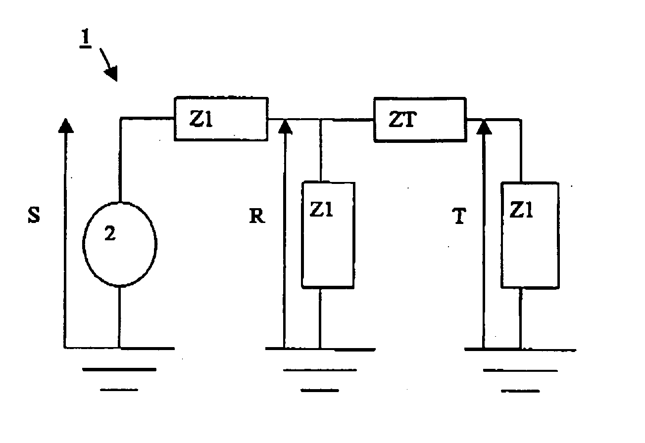
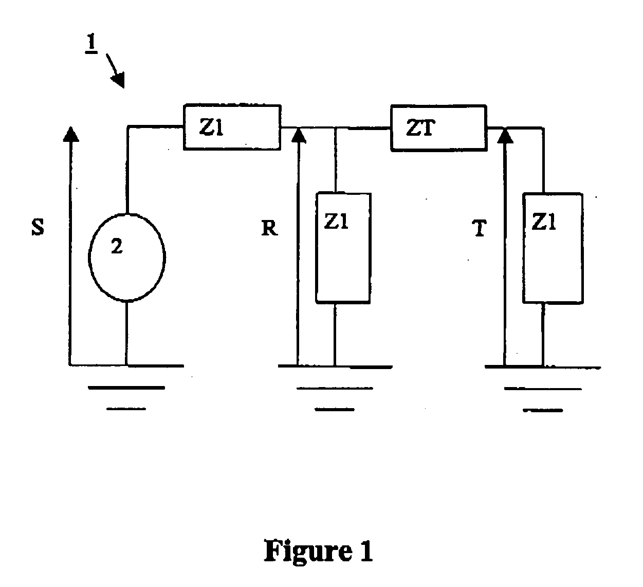
[0043] FIG. 1 is described above with reference to the state of the art. The FRA measurements described below were all taken using an analysis circuit of the kind shown in FIG. 1.

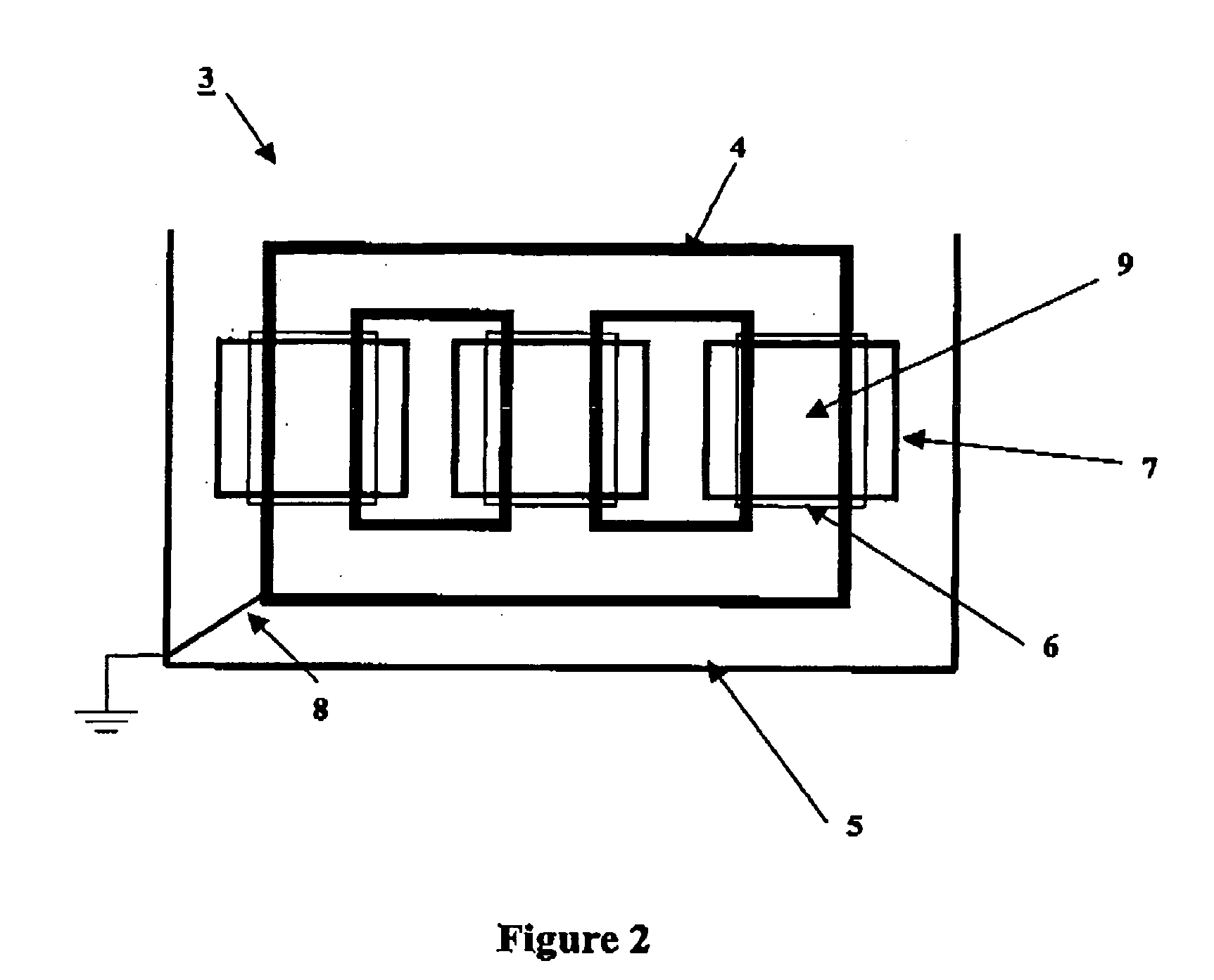
[0044] FIG. 2 is a diagram of a three-phase transformer 3.

[0045] The three-phase transformer 3 comprises:

[0046] a magnetic circuit 4;

[0047] a tank 5;

[0048] three low voltage windings 6; and

[0049] three high voltage windings 7.

[0050] Each pair of high and low voltage windings corresponds to one phase of the transformer and is associated with a respective core 9 of the circuit 4. The three phases of the transformer are referred to below respectively as A, B, and C.

[0051] The magnetic circuit 4 and the tank 5 are connected together by a connection 8 and they are both grounded.

[0052] Three impedance measurements can be performed respectively for high voltage and for low voltage.

[0053] Thus, if a fault is suspected on one of the high voltage windings of the transformer, the gain of that winding is measured as a ...


PUM


Abstract

The present invention relates to a method of diagnosing a fault on a transformer winding by using frequency response analysis. The method comprises the steps of: measuring the impedance on said winding as a function of frequency, said measurement being represented in the form of a first voltage gain; comparing said impedance measurement with a reference measurement represented in the form of a second voltage gain, said comparison including a step of calculating three first parameters, each of said three first parameters being a correlation coefficient, between said first and second gains over three different frequency ranges. The method further comprises a step of determining the relative variation of at least a fourth parameter, said fourth parameter being a physical magnitude characteristic of said transformer, said relative variation being obtained by comparing said first and second gains.

Description

[0001] The present invention relates to a method of diagnosing a fault on a transformer winding by using frequency response analysis (FRA). The present invention is more particularly adapted to power transformers.[0002] Power transformers (such as transformers having primary voltages of several hundreds of kilovolts (kV) and delivering powers lying in the range a few megavolt amps (MVA) to several hundred MVA) are extremely expensive pieces of equipment in systems for interconnecting electricity transmission networks or "grids". It is therefore very useful to be able to keep such transformers in service for as long as possible, since a transformer breakdown or fault can have major economic consequences due to the distribution network being interrupted.[0003] In addition, faults ouch as short circuits can run the risk of explosion or fire.[0004] It is therefore very important to be able to determine the presence of a fault associated with a transformer winding.[0005] A known solution...

Claims


Application Information

Patent Timeline
Patent Type & Authority Applications(United States)
IPC IPC(8): G01R31/06G01R31/28
CPCG01R31/2829G01R31/027G01R31/62
Inventor RYDER, SIMON
Owner ALSTOM TECH LTD
Learn More