Magnetic tape and method for manufacturing the same

a technology of magnetic tape and cut surface, which is applied in the direction of manufacturing tools, magnetic materials for record carriers, instruments, etc., can solve the problems of affecting the quality of magnetic tape, the risk of a part of the cut surface of the magnetic tape peeling and dropping off the cut surface, and the inability to sufficiently diminish the irregular raised and depressed pattern of the cut surfa

Inactive Publication Date: 2004-09-09
TDK CORPARATION
View PDF5 Cites 16 Cited by
  • Summary
  • Abstract
  • Description
  • Claims
  • Application Information

AI Technical Summary

Benefits of technology

[0010] To the contrary, the inventors of the present invention further found that in the case where the ratio of the broken region included in the lower blade side cut surface of the magnetic tape was 40% to 65%, it was possible to suppress the irregular raised and depressed pattern of the cut surface of the magnetic tape on the side of the lower blade and the irregular raised and depressed pattern of the cut surface of the magnetic tape on the side of the upper blade to within an acceptable range and therefore, if a cutting start angle between the disk-like upper blade and the disk-like lower blade overlapping each other and rotating in opposite directions at the time that cutting of the broad magnetic tape fed to a portion therebetween was started was set so that the lower blade side cut surface of the magnetic tape to be manufactured by cutting the broad magnetic tape using the disk-like upper blade and the disk-like lower blade included 40% to 65% of the broken region and the broad magnetic tape was cut, thereby manufacturing the magnetic tape, then even if guide members of a data recording apparatus or a data reproducing apparatus came into contact with the cut surface of the magnetic tape on the side of the lower blade or the upper blade, it was possible to prevent a part of the cut surface of the magnetic tape from peeling and dropping off the cut surface of the magnetic tape.
[0015] In a further study done by the inventors of the present invention, it was found that in the case where the ratio of the broken region included in the lower blade side cut surface of the magnetic tape to be formed by cutting the broad magnetic tape by the upper blade and the lower blade was 50% to 60%, both the irregular raised and depressed pattern of the magnetic tape on the side of the lower blade and the irregular raised and depressed pattern of the magnetic tape on the side of the upper blade became smaller. Therefore, since in this preferred aspect of the present invention the cutting start angle between the disk-like upper blade and the disk-like lower blade overlapping each other and rotating in opposite directions at the time that cutting of the broad magnetic tape fed to a portion between the upper blade and the lower blade by the upper blade and the lower blade is started is set so that the lower blade side cut surface of the magnetic tape to be formed by cutting the broad magnetic tape by the upper blade and the lower blade includes 50% to 60% of a region formed by cutting the magnetic tape by a breaking force, thereby cutting the broad magnetic tape, it follows that even if guide members of a data recording apparatus or a data reproducing apparatus come into contact with the cutting surface of the magnetic tape on the side of the lower blade or the upper blade, it is possible to reliably prevent a part of the cut surface of the magnetic tape from peeling and dropping off the cut surface.
[0017] As pointed out above, in one study done by the inventors of the present invention, it was found that in the case where the ratio of the broken region included in the lower blade side cut surface of the magnetic tape formed by cutting the broad magnetic tape by the upper blade and the lower blade overlapping each other and rotating in opposite directions was 50% to 60%, both the irregular raised and depressed pattern of the magnetic tape on the side of the lower blade and the irregular raised and depressed pattern of the magnetic tape on the side of the upper blade were small, and even if guide members of a data recording apparatus or a data reproducing apparatus came into contact with the cutting surface of the magnetic tape on the side of the lower blade or the upper blade, it was possible to effectively prevent a part of the cut surface of the magnetic tape from peeling and dropping off the cut surface. However, the inventors of the present invention further found that in the case where the cutting start angle between the upper blade and the lower blade exceeded 12 degrees, the irregular raised and depressed pattern formed on the cut surface of the magnetic tape on the side of the upper blade became larger and when the guide members of a data recording apparatus or a data reproducing apparatus came into contact with the cutting surface of the magnetic tape on the side of the upper blade, there arose a risk of a part of the cut surface of the magnetic tape peeling and dropping off the cut surface.
[0018] Therefore, since in this preferred aspect of the present invention the cutting start angle between the disk-like upper blade and the disk-like lower blade overlapping each other and rotating in opposite directions at the time that cutting of the broad magnetic tape fed to a portion therebetween is started is set to be equal to or less than 12 degrees. so that a lower blade side cut surface of the magnetic tape to be formed by cutting the broad magnetic tape by the upper blade and the lower blade includes 40% to 65% of a region formed by cutting the magnetic tape by a breaking force and the broad magnetic tape is cut by the upper blade and the lower blade, thereby manufacturing a magnetic tape, it follows that even if guide members of a data recording apparatus or a data reproducing apparatus come into contact with the cutting surfaces of the magnetic tape on both sides of the upper blade and the lower blade, it is possible to effectively prevent a part of the cut surface of the side of the upper blade and a part of the cut surface of the magnetic tape on the side of the lower blade from peeling and dropping off the cut surfaces.
[0021] Therefore, since in this preferred aspect of the present invention the cutting start angle between the disk-like upper blade and the disk-like lower blade overlapping each other and rotating in opposite directions at the time that cutting of the broad magnetic tape fed to a portion therebetween is started is set to be equal to or larger than 9 degrees and less than 12 degrees so that a lower blade side cut surface of the magnetic tape to be formed by cutting the broad magnetic tape by the upper blade and the lower blade includes 40% to 65% of a region formed by cutting the magnetic tape by a breaking force and the broad magnetic tape is cut by the upper blade and the lower blade, thereby manufacturing a magnetic tape, it follows that even if guide members of a data recording apparatus or a data reproducing apparatus come into contact with the cutting surfaces of the magnetic tape on both sides of the upper blade and the lower blade, it is possible to reliably prevent a part of the cut surface of the side of the upper blade and a part of the cut surface of the magnetic tape on the side of the lower blade from peeling and dropping off the cut surfaces.
[0024] In the present invention, the magnetic tape includes a support, one or more magnetic recording layers formed on one surface of the support and a back coat layer formed on the other surface of the support. However, the magnetic tape may further include an undercoat layer between the magnetic recording layer and the support for improving adhesiveness between the magnetic recording layer and the support.

Problems solved by technology

Therefore, there is some risk of a part of the cut surface peeling off and dropping from the cut surface of the magnetic tape.
It is impossible to sufficiently diminish the irregular raised and depressed pattern of the cut surface of a magnetic tape only by chamfering the upper blade or the lower blade.
However, the inventors of the present invention further found that in the case where the cutting start angle between the upper blade and the lower blade exceeded 12 degrees, the irregular raised and depressed pattern formed on the cut surface of the magnetic tape on the side of the upper blade became larger and when the guide members of a data recording apparatus or a data reproducing apparatus came into contact with the cutting surface of the magnetic tape on the side of the upper blade, there arose a risk of a part of the cut surface of the magnetic tape peeling and dropping off the cut surface.
Therefore, in the case where the degree of the projection of the cut surface exceeds a predetermined level, the guide members of the data recording apparatus or the data reproducing apparatus come into contact with the projected portions of the cut surfaces of the computer data back-up tape 1 when data are to be recorded or when data are to be reproduced, whereby there arises a risk of the projected portions of the cut surfaces dropping off the computer data back-up tape 1.

Method used


Image

  • Magnetic tape and method for manufacturing the same
  • Magnetic tape and method for manufacturing the same
  • Magnetic tape and method for manufacturing the same

Examples


working example 1

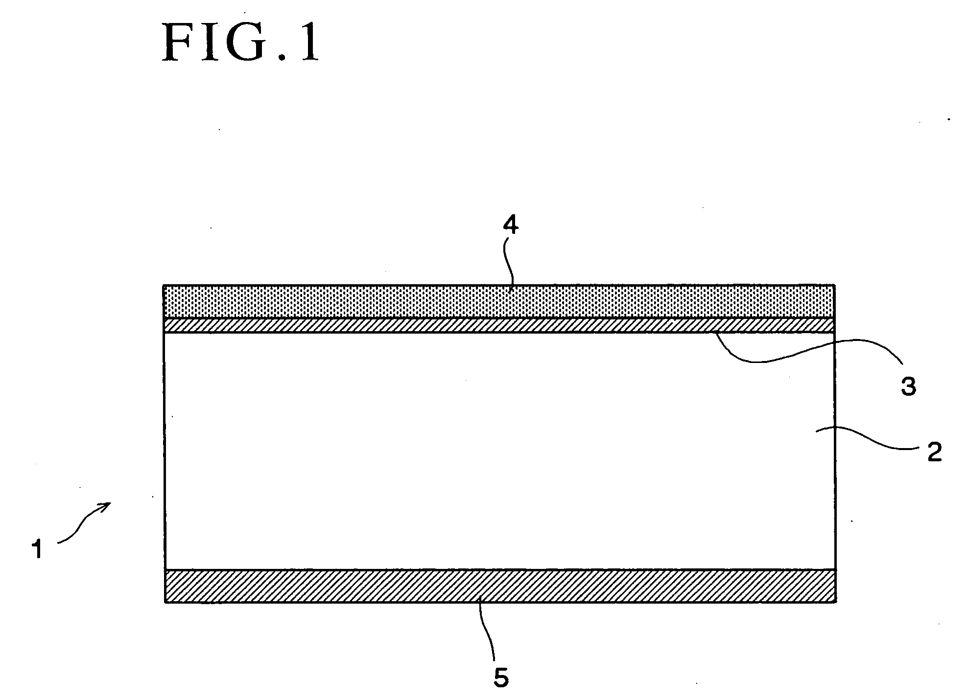
[0061] A broad magnetic tape was manufactured by forming an under coat layer 3 having a thickness of 2 .mu.m and a magnetic recording layer 4 having a thickness of 0.15 .mu.m on one surface of a broad support 2 made of polyethylene terephthalate and having a width of 500 mm and a thickness of 6.1 .mu.m and forming a back coat layer 5 having a thickness of 0.5 .mu.m on the other surface of the support 2, thereby manufacturing a broad magnetic tape.

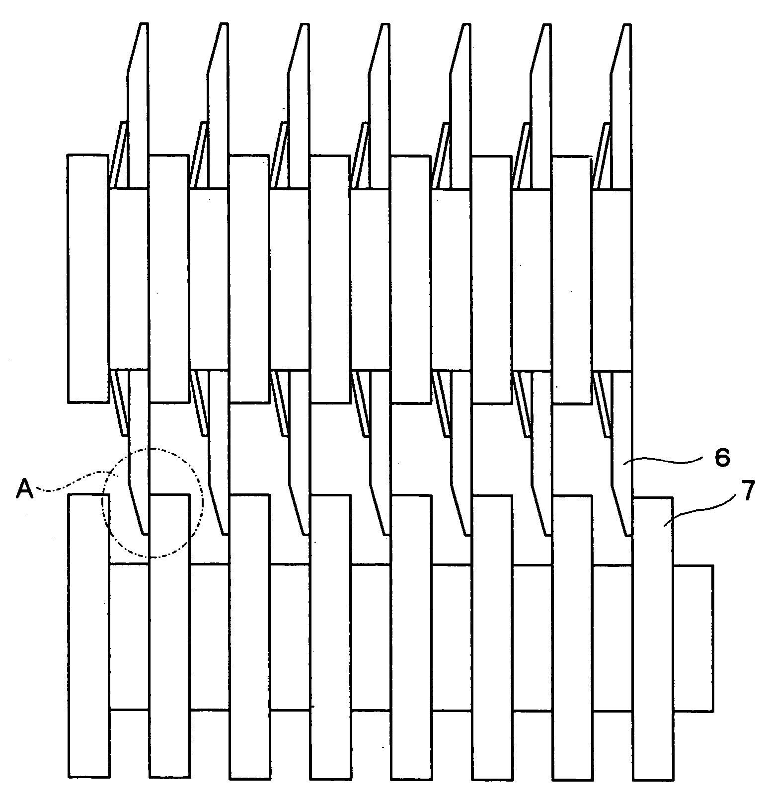
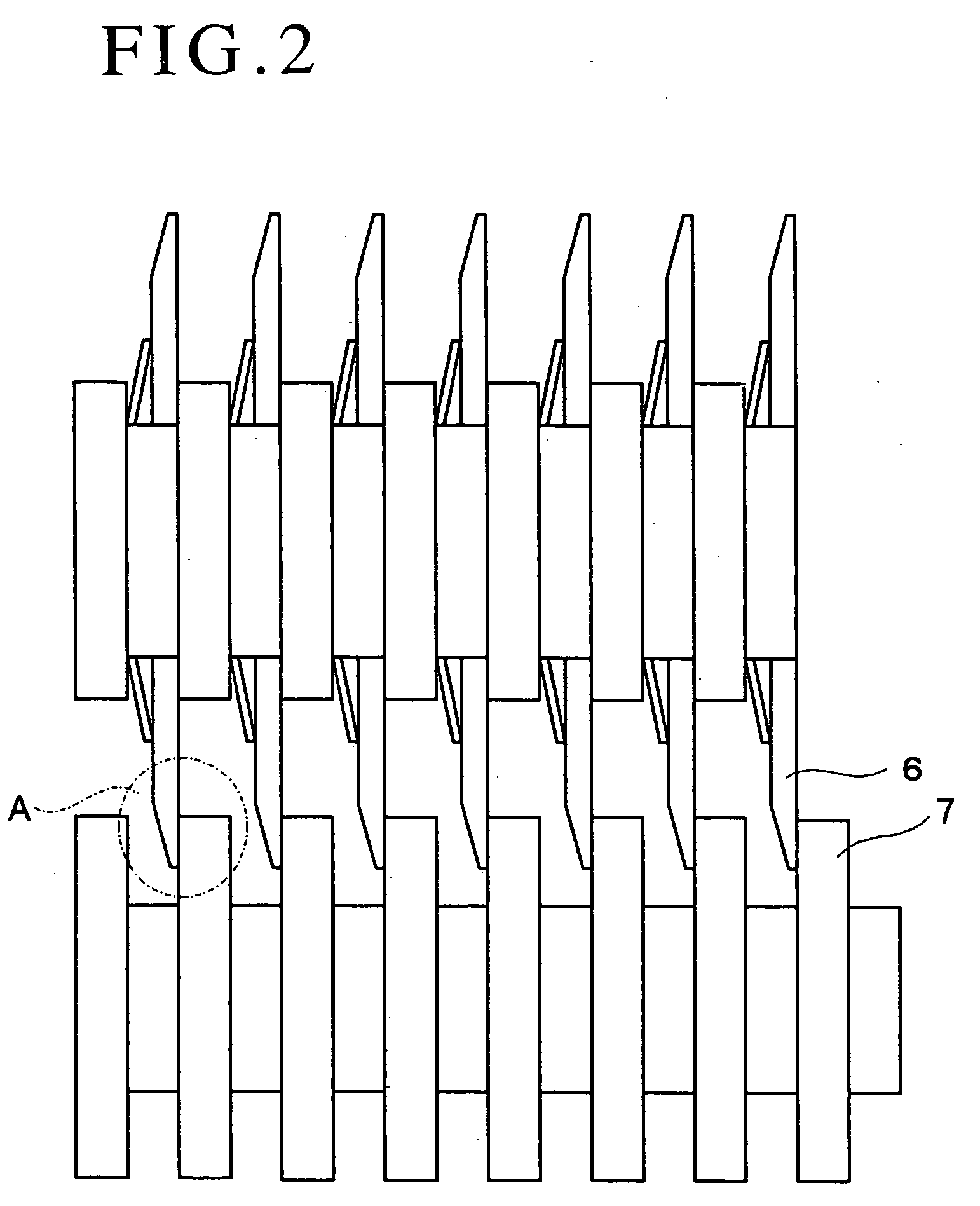
[0062] Then, the broad magnetic tape was cut using a pair of cutting units 8 each including an upper blade 6 having a diameter of 150 mm and a lower blade 7 having a diameter of 150 mm, thereby manufacturing a computer data back-up tape 1 having a width of 12.65 mm.

[0063] An upper blade 6 was employed whose surface facing the lower blade 7 was substantially parallel with the surface of the lower blade 7 facing the upper blade 6 and whose surface opposite from the surface facing the lower blade 7 was an inclined surface formed so that the th...

working example 2

[0070] A broad magnetic tape was manufactured by forming an under coat layer 3 having a thickness of 2 .mu.m and a magnetic recording layer 4 having a thickness of 0.15 .mu.m on one surface of a broad support 2 made of polyethylene terephthalate and having a width of 500 mm and a thickness of 6.1 .mu.m and forming a back coat layer 5 having a thickness of 0.5 .mu.m on the other surface of the support 2. The thus obtained broad magnetic tape was cut using a pair of cutting units 8 each including an upper blade 6 having a diameter of 100 mm and a lower blade having a diameter of 100 mm, thereby manufacturing a computer data back-up tape 1.

[0071] An upper blade 6 was employed whose surface facing the lower blade 7 was substantially parallel with the surface of the lower blade 7 facing the upper blade 6 and whose surface opposite from the surface facing the lower blade 7 was an inclined surface formed so that the thickness of the upper blade 6 gradually decreased toward its tip end port...


PUM

PropertyMeasurementUnit
cutting start angleaaaaaaaaaa
thicknessaaaaaaaaaa

Abstract

A method for manufacturing a magnetic tape includes the steps of feeding a broad magnetic tape including a broad support formed with a magnetic recording layer on one side thereof and a back coat layer on the other surface thereof to a portion between a disk-like upper blade and a disk-like lower blade overlapping each other and rotating in opposite directions and cutting the broad magnetic tape into magnetic tapes each having a predetermined width, which method for manufacturing a magnetic tape further includes a step of setting a cutting start angle between the disk-like upper blade and the disk-like lower blade overlapping each other and rotating in opposite directions at the time that cutting of the broad magnetic tape fed to a portion between the upper blade and the lower blade by the upper blade and the lower blade is started so that a lower blade side cut surface of the magnetic tape to be formed by cutting the broad magnetic tape includes 40% to 65% of a region formed by cutting the magnetic tape by a breaking force, thereby cutting the broad magnetic tape. According to the above method, it is possible to manufacture a magnetic tape which can minimize an irregular raised and depressed pattern of a cut surface of a magnetic tape.

Description

[0001] The present invention relates to a magnetic tape and a method for manufacturing a magnetic tape and, particularly, to a magnetic tape and a method for manufacturing a magnetic tape which can minimize an irregular raised and depressed pattern of a cut surface of a magnetic tape obtained by feeding a broad magnetic tape to a portion between a disk-like upper blade and a disk-like lower blade overlapping each other and rotating in the opposite directions and cutting it along the longitudinal direction thereof, and effectively prevent a part of the cut surface of the magnetic tape from peeling off and dropping from the cut surface of the magnetic tape when data are to be recorded in the magnetic tape or data are to be reproduced from the magnetic tape due to the irregular raised and depressed pattern of the cut surface of the magnetic tape.DESCRIPTION OF THE PRIOR ART[0002] Usually, a magnetic tape is manufactured by forming a magnetic recording layer on one surface of a broad su...

Claims


Application Information

Patent Timeline
Patent Type & Authority Applications(United States)
IPC IPC(8): B26D1/24B26D1/00G11B5/78G11B5/84
CPCB26D1/0006B26D2001/0066B26D2001/0053B26D2001/0046Y10T83/04Y10T83/0605Y10T83/783
Inventor SHOUDAI, SADAYUKIKIKUCHI, TSUTOMU
Owner TDK CORPARATION
Why Eureka
Try Eureka