Objective lens driving device for optical head
- Summary
- Abstract
- Description
- Claims
- Application Information
AI Technical Summary
Benefits of technology
Problems solved by technology
Method used
Image
Examples
first embodiment
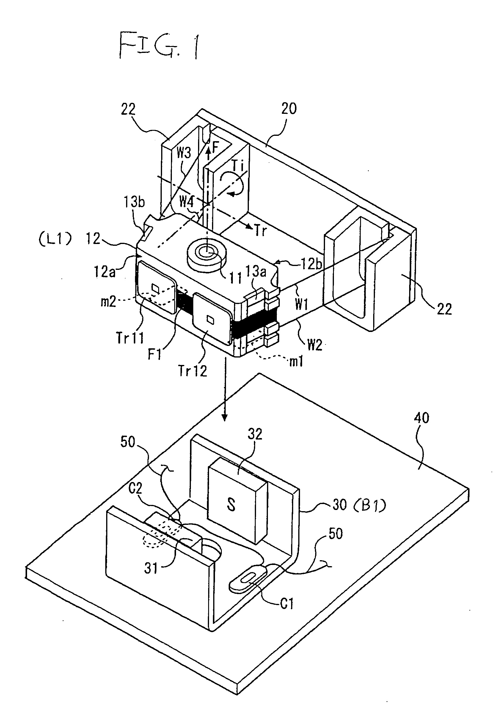
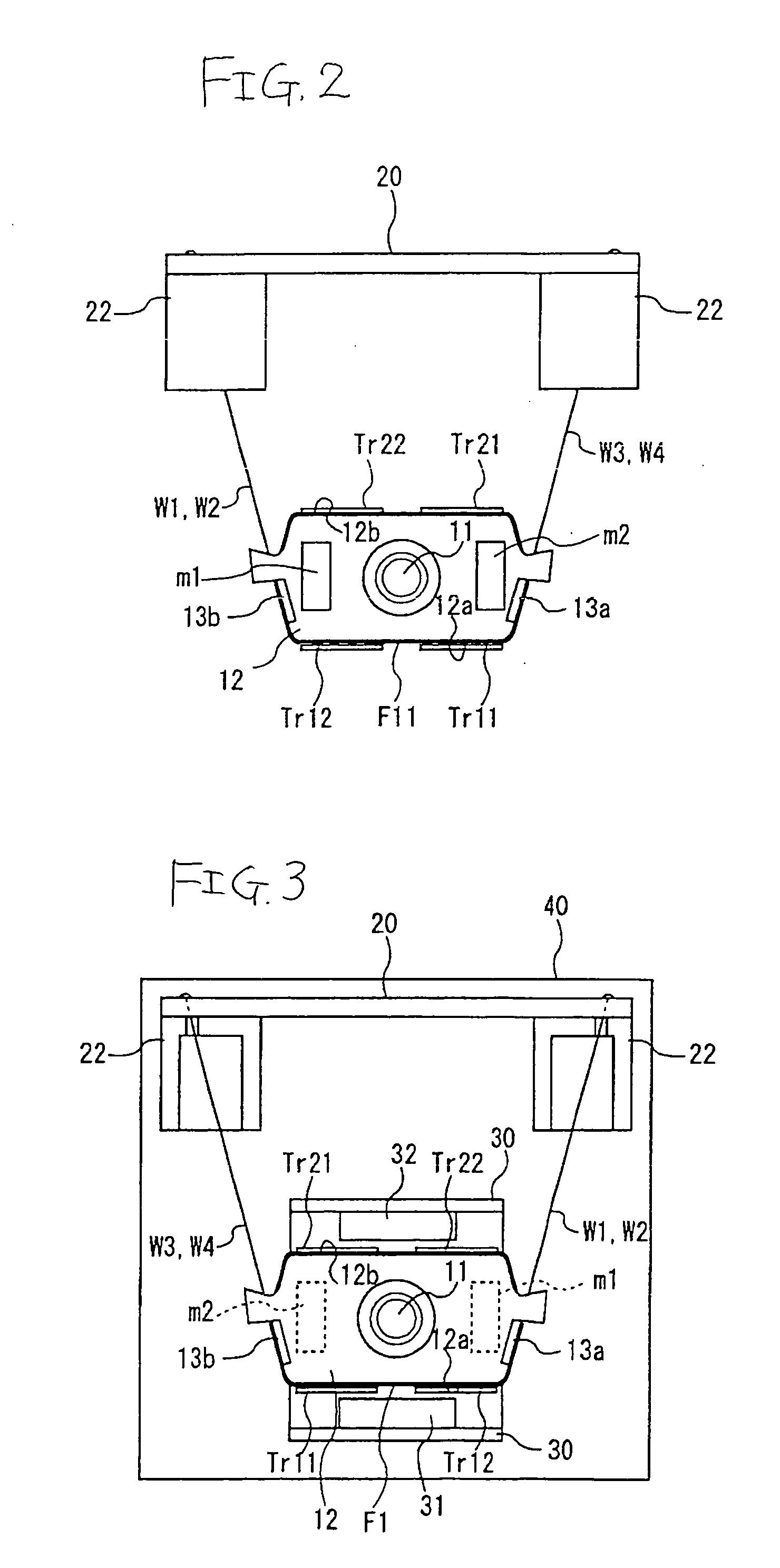
[0029] FIG. 1 is an exploded perspective view showing an objective lens driving device for an optical head in the invention, FIG. 2 is a bottom view showing a lower face of a lens holder, and FIG. 3 is a plan view of this driving device.
[0030] The objective lens driving device in this embodiment aims to perform corrections of an objective lens of an optical head (also called as "an optical pickup") in a driving apparatus for a recordable DVD (Digital Versatile Disc) such as DVD-R, DVD-RW, etc., by conducting minute driving in three axial directions, namely, in a light focus direction F, in a radial direction (a track direction) Tr of a disk which intersects with data rows on the disk, and in a tilt angle direction Ti which corresponds to a tilt in the radial direction of the disk.
[0031] The objective lens driving device in this embodiment includes an objective lens 11 for condensing laser lights irradiated from the exterior, a lens holder 12 for holding this objective lens 11, a foc...
second embodiment
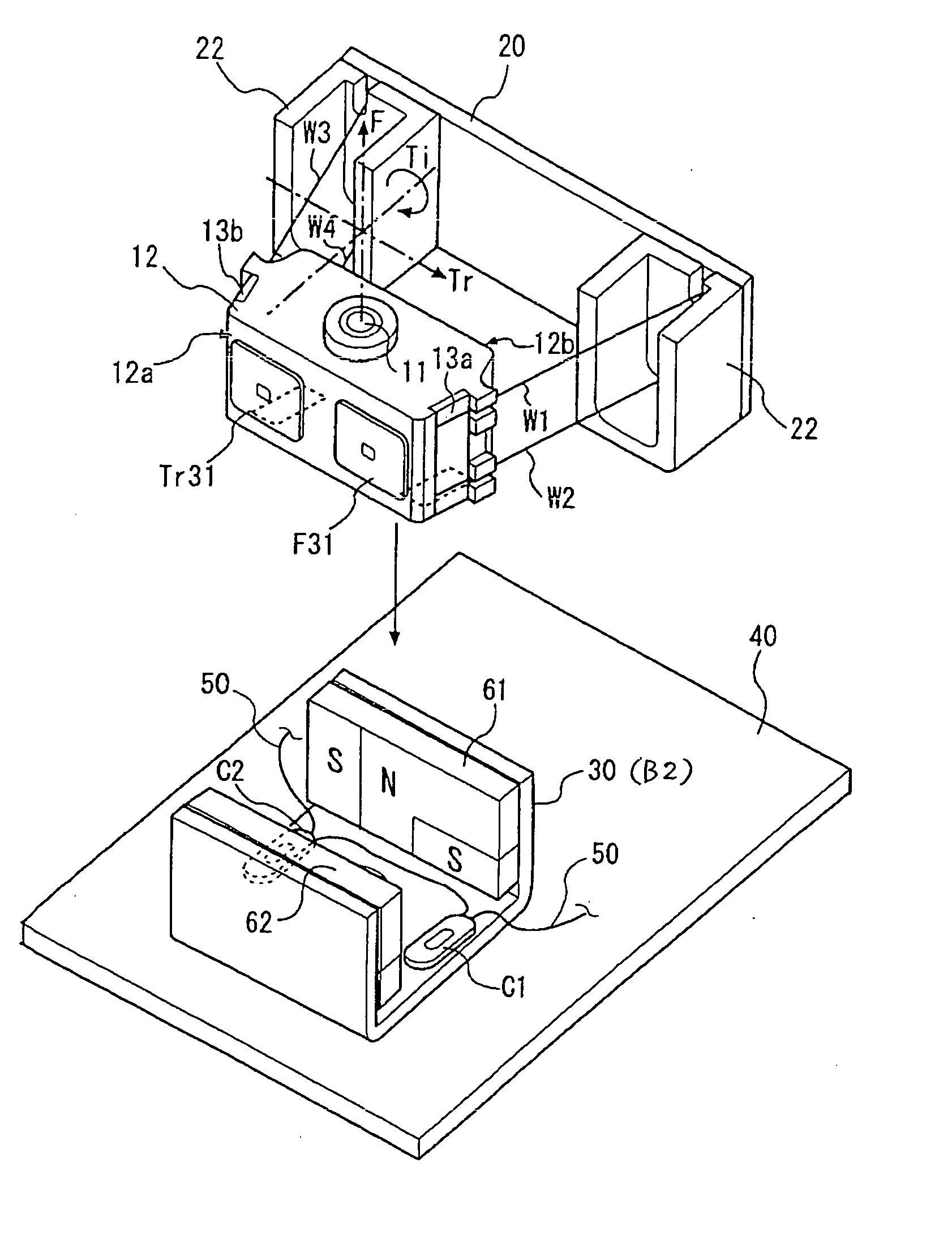
[0045] Referring now to FIGS. 4 to 7, an objective lens driving device in a second embodiment will be described.
[0046] It is to be noted that the same components as in the first embodiment will be denoted with the same reference numerals, and their detailed description will be omitted.
[0047] FIG. 4 is an exploded perspective view showing an objective lens driving device for an optical head in the second embodiment, FIGS. 5 and 6 are views for explaining positional relation of magnetic poles appearing in magnets with respect to square type flat coils fixed to the lens holder, and FIG. 7 is a bottom view of the lens holder which constitutes the essential part of the objective lens driving device.
[0048] In the second embodiment, different from the first embodiment, there is provided no focusing coil F1 which is wound around the peripheral face of the lens holder 12 in a direction perpendicular to the focus direction.
[0049] In the second embodiment, of two pairs of square type flat coil...
modified example
[0061] FIG. 8 shows another embodiment of the objective lens driving device according to the invention.
[0062] Although the yoke members for making the lines of induction extending from the magnets 31, 32 more straight are not provided in the first embodiment as shown in FIG. 1, it is also possible to construct the device in such a manner that the yoke members 30A, 30B are uprightly provided on the holder body 30, as shown in FIG. 8, while the lens holder 12 is formed with through holes 12A, 12B for the yoke members 30A, 30B to pass through. In this case, the holder body 30 is formed of magnetic material.
[0063] By providing the yoke members 30A, 30B in this manner, the lines of induction extending from the magnets 31, 32 can be made more straight as compared with the case where the yoke members 30A, 30B are not provided. As the results, drive and control of the objective lens by the control currents passed through the square type flat tracking coils Tr11, Tr12, Tr21, Tr22 and the foc...
PUM
 Abstract
Description
Claims
Application Information
 - R&D
- Intellectual Property
- Life Sciences
- Materials
- Tech Scout
- Unparalleled Data Quality
- Higher Quality Content
- 60% Fewer Hallucinations
Browse by: Latest US Patents, China's latest patents, Technical Efficacy Thesaurus, Application Domain, Technology Topic, Popular Technical Reports.
© 2025 PatSnap. All rights reserved.Legal|Privacy policy|Modern Slavery Act Transparency Statement|Sitemap|About US| Contact US: help@patsnap.com


