
Adhesive roller construction

a technology of adhesive rollers and rollers, applied in the direction of film/foil adhesives, cleaning equipments, transportation and packaging, etc., can solve the problems of disadvantageously time-consuming, difficult to remove a single layer of adhesive strips in a single piece without, and disadvantageously messy, so as to facilitate the removal of individual layers and facilitate manual manipulation. , the effect of enhancing the accessibility of users

Inactive Publication Date: 2004-10-07
THE EVERCARE
View PDF26 Cites 32 Cited by
  • Summary
  • Abstract
  • Description
  • Claims
  • Application Information

AI Technical Summary

Benefits of technology

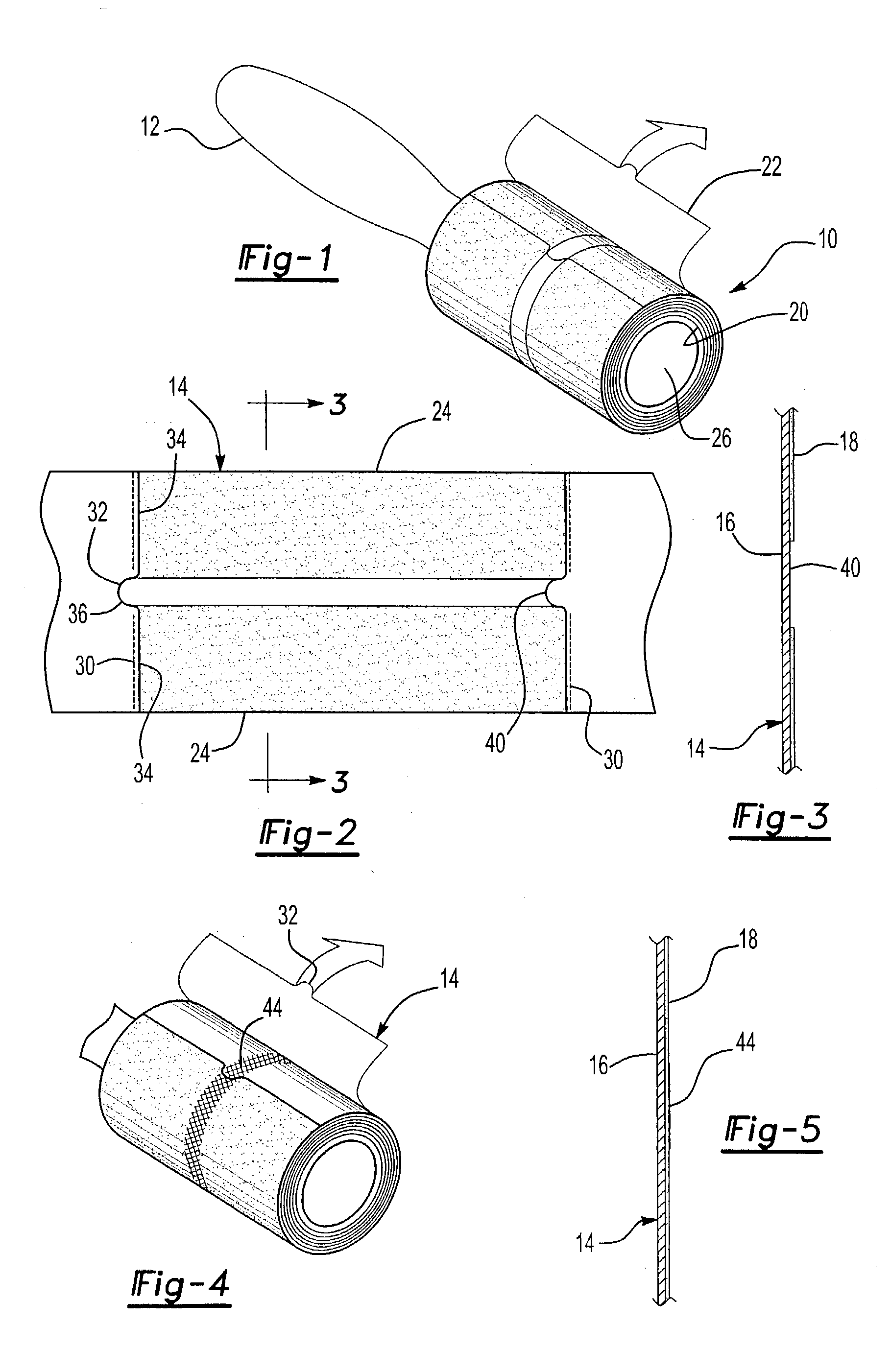
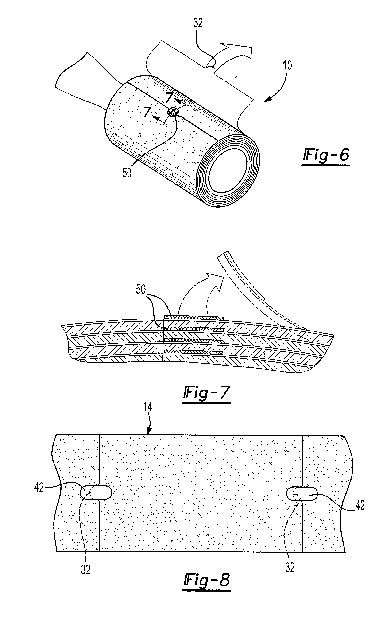
[0012] This tab, in turn, registers with a non-adhesive portion of the immediately adjacent inner layer of the roll. Since the tab registers with a non-adhesive portion on the roll, the tab "pops" out from the adhesive roll. As such, the tab provides a portion that can be easily manually manipulated by the user to facilitate the removal of the individual layers of the adhesive roll as the adhesive on those layers become depleted.
[0013] Optionally, the tab may be created with a substrate having shape members in a direction concave to the surface of the adhesive roll. Such a substrate would ensure that the tab protrudes outwardly from the adhesive roll for enhanced accessibility for the user.

Problems solved by technology

In practice, however, it has proven somewhat difficult to remove a single layer of the strip from the roll in a single piece without tearing the layer in the process.
The primary difficultly in removing the layer from the roll is initiating the separation of the layer from its immediately adjacent inner layer.
This is disadvantageously time consuming and can be somewhat messy.

Method used


Image

  • Adhesive roller construction
  • Adhesive roller construction
  • Adhesive roller construction

Examples


Embodiment Construction

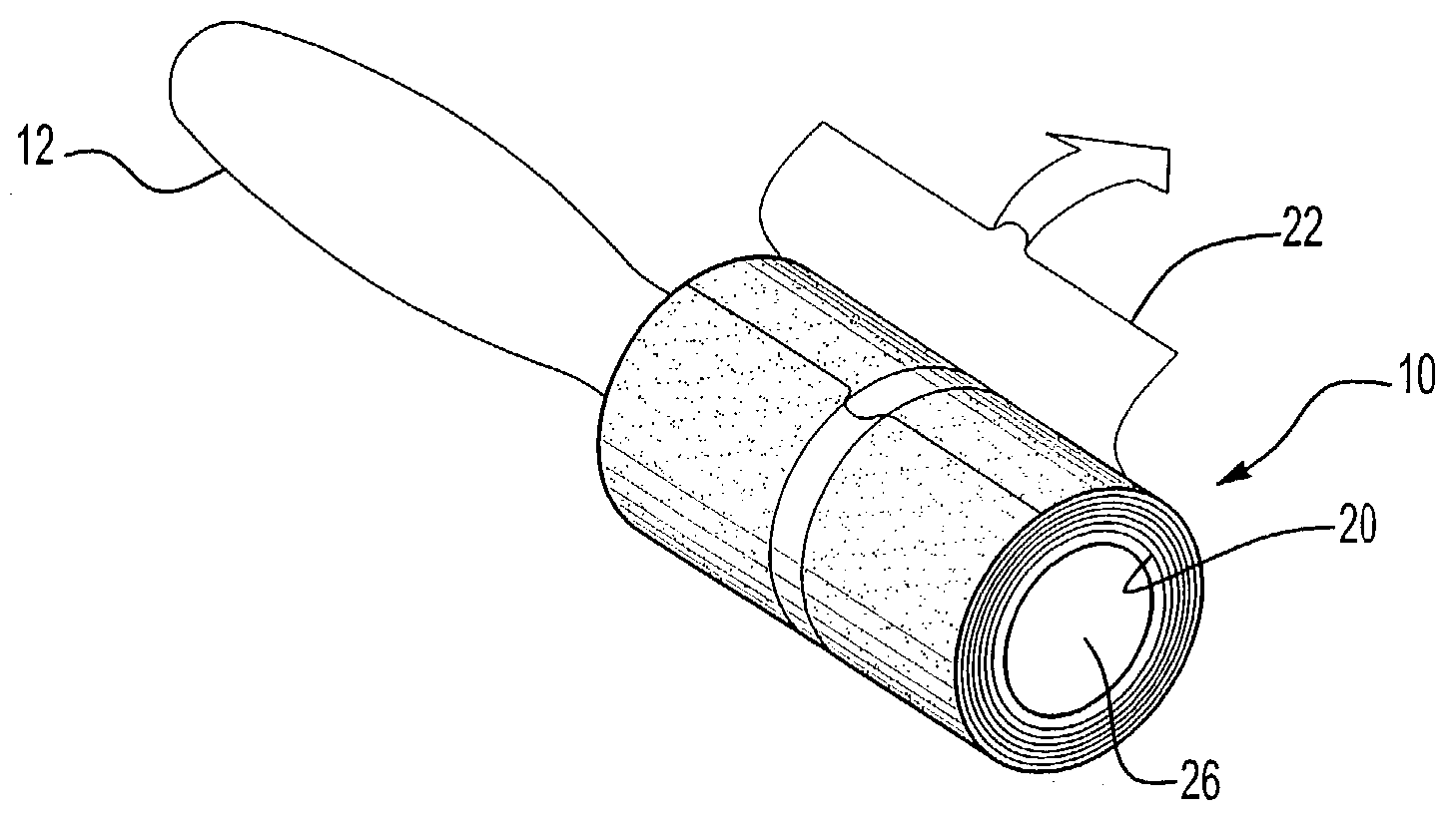
[0027] With reference first to FIGS. 1-3, a preferred embodiment of the adhesive roller construction 10 of the present invention is shown rotatably mounted to a handle 12 in any conventional fashion. The adhesive roller construction 10 includes an elongated strip 14 having a backing layer 16 and an adhesive layer 18 on at least a portion of one side of the backing layer 16. The elongated strip 14 also includes a first end 20 (FIG. 1), a second end 22 and two spaced apart sides 24. The adhesive layer 18 may cover the entire surface of one side of the backing layer 16 or, alternatively, a longitudinally extending dry, non-adhesive, edge may be provided along one, or both, edges 24.

[0028] As best shown in FIG. 1, the strip 14 is wound from its first end 20 and to its second end 22 into a tubular and cylindrical roll so that the adhesive layer 18 faces outwardly. Preferably, the strip 14 is wound about a tubular and cylindrical roller support 26 which is made of any suitable material, s...


PUM

PropertyMeasurementUnit
shape memoryaaaaaaaaaa
plasticaaaaaaaaaa
lengthaaaaaaaaaa

Abstract

An adhesive roller having an elongated strip with a backing layer and an adhesive layer overlying at least a portion of one side of the backing layer. The strip has a first end, a second end, and two spaced apart sides. The strip is wound from its first end and to its second end into a tubular cylindrical roll in which multiple layers of the strip overlap each other. An elongated perforation is formed transversely across the strip at spaced intervals therealong. This perforation, furthermore, includes an outwardly protruding tab at a position intermediate the ends of the perforation. This tab registers with a non-adhesive portion of an immediately inner layer of the strip so that the tab pops out from the roll to facilitate removal of the individual layers of the roller.

Description

[0001] I. Field of the Invention[0002] The present invention relates generally to adhesive rollers and, more particularly, to such a roller used for detritus removal.[0003] II. Description of the Prior Art[0004] Lint rollers have long been known and widely used for removing detritus, such as pet hair, dandruff, lint and the like, from clothing, furniture, floors, etc. These previously known lint rollers typically comprise a handle having a tubular and cylindrical tape roll rotatably mounted to the handle.[0005] Many of the previously known adhesive rollers for detritus removal comprise a continuous strip having a backing and with an adhesive layer provided on one side of the backing. This layer is then wound into a tubular and cylindrical roll, typically around a tubular roller support, so that the strip overlaps itself to form multiple layers. As the adhesive becomes depleted from use, a portion of the strip is then torn away from the roll to expose fresh adhesive. This process is ...

Claims


Application Information

Patent Timeline
Patent Type & Authority Applications(United States)
IPC IPC(8): A47L25/00B65D65/28C09J7/20
CPCA47L25/005C09J7/02C09J2201/20C09J2201/28C09J7/20C09J2301/18C09J2301/204
Inventor MCKAY, NICHOLAS D. JR.
Owner THE EVERCARE
Learn More