Form panel for placing concrete

Inactive Publication Date: 2004-10-14
FUKUBI KAGAKU IND
View PDF14 Cites 24 Cited by
  • Summary
  • Abstract
  • Description
  • Claims
  • Application Information

AI Technical Summary

Benefits of technology

0017] A form panel for placing concrete of the present invention is a plastic form panel for placing concrete comprising hollow sheathing section, one side of which forms a concrete placing surface, and hollow side panel sections bent out at right angles from both side edges of the sheathing section on an opposite side of the sheathing section to the concrete placing surface, wherein at least one projecting section which extends in a vertical direction is provided on an outside surface of at least one of t

Problems solved by technology

However, disadvantages of these plywood form panels are that (i) a nailing operation needs to be performed when securing the battens or connecting form panels, causing poor workability, (ii) the form panel is easily damaged by the nailing, and by concrete stripper applied to the front surface of the sheathing board, and as such can only be reused a limited number of times (approximately 5 times, for example), and (iii) form panels which can no longer be reused cannot be recycled as wood, and can only be dismantled and incinerated.
Consequently, when formwork fittings which tend to concentrate pressure on a single point are used, such as the P-Cones 21 and the clamps 23 used with conventional plywood form panels, then the form panel 10 is easily damaged.
For such reasons, the use of these conventional formwork fittings with plastic form panels is problematic, and it is necessary to use special fittings with a specific shape.
Accordingly, the installation of plastic form panels in the configuration sown in FIG. 18 is difficult to achieve.
Furthermore, the inability to

Method used


Image

  • Form panel for placing concrete
  • Form panel for placing concrete
  • Form panel for placing concrete

Examples


embodiment 2

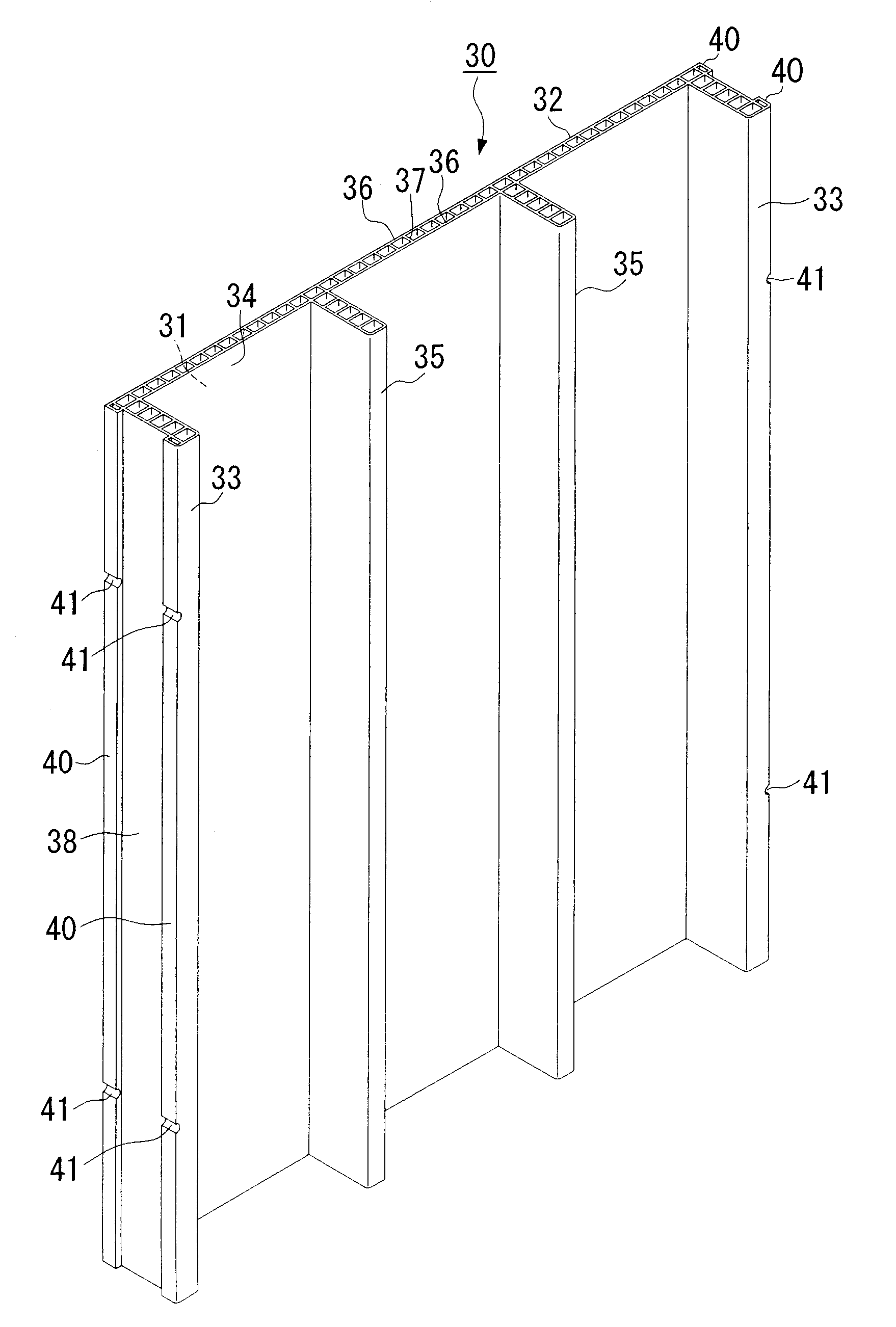
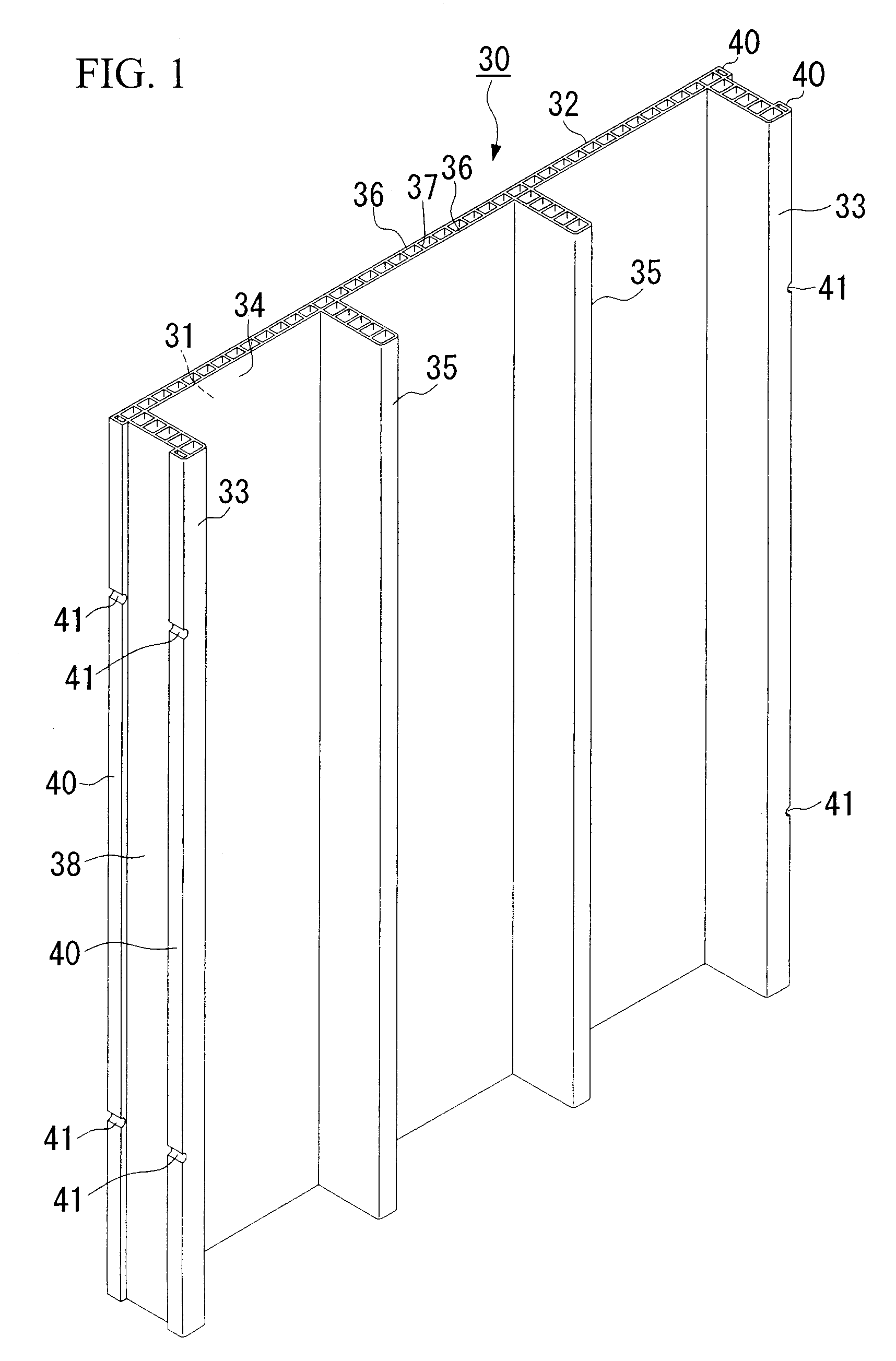
[0079] FIG. 7 shows another example of a plastic form panel for placing concrete of the present invention. This form panel 50 comprises generally a hollow sheathing section 52, one side of which forms a concrete placing surface 51, hollow side panel sections 53 bent out at right angles from both side edges of the sheathing section 52 on the opposite side of the sheathing section 52 to the concrete placing surface 51, two hollow projecting sections 60 extending in the vertical direction, provided on both side edges of an outside surface 58 of the side panel sections 53, and two hollow reinforcing panel sections 55 provided on a rear surface 54 of the sheathing section 52 which are parallel to the side panel sections 53. Here, the sheathing section 52, the side panel sections 53 and the reinforcing panel sections 55 are formed from hollow panels in which two panels 56 and a plurality of long reinforcing ribs 57 connecting these panels, are formed as an integrated unit.

[0080] Furthermo...

embodiment 3

[0113] FIG. 12 and FIG. 13 show another example of a plastic form panel for placing concrete of the present invention. This form panel 70 comprises generally a hollow sheathing section 72, one side of which forms a concrete placing surface 71, hollow side panel sections 73 bent out at right angles from both side edges of the sheathing section 72 on the opposite side of the sheathing section 72 to the concrete placing surface 71, two hollow projecting sections 81and 82 extending in the vertical direction, provided at the side edges of an outside surface 78 of the side panel sections 73, and four hollow reinforcing panel sections 75 which are parallel to the side panel sections 73.

[0114] Here, one of the sides of the projecting section 61 nearest the concrete placing surface 71 is coplanar with the concrete placing surface 71 of the sheathing section 72.

[0115] Furthermore, an inclined surface 83 is formed on the side surface of the projecting section 82 which faces the projecting sect...


PUM

PropertyMeasurementUnit
Transparencyaaaaaaaaaa
Durabilityaaaaaaaaaa

Abstract

The form panel for placing concrete of the present invention is a form panel (30) comprising a hollow sheathing section (32) made of plastic, one side of which forms a concrete placing surface (31), and hollow side panel sections (33) bent out at right angles from both side edges of the sheathing section (32) on an opposite side of the sheathing section (32) to the concrete placing surface (31), wherein projecting sections (40) which extend in a vertical direction are provided on an outside surface (38) of the side panel section (33), and one of the sides of one of the projecting sections (40) is coplanar with the concrete placing surface (31) of the sheathing section (32), and on the projecting sections (40), notches (41) are formed at respectively the same position and orthogonal to the longitudinal direction of the projecting sections (40). This type of form panel (30)allows the formwork fittings used with conventional plywood form panels to be used at the time of erection (installation), is lightweight and has good workability, is durable, does not easily leak concrete, and can be recycled.

Description

[0001] The present invention relates to a plastic form panel for placing concrete, and relates specifically of a recyclable plastic form panel for placing concrete which allows the same fittings used in conventional plywood form panels comprising veneer plywood and the like, such as P-Cones and Form Ties (registered trademarks), to be used.[0002] Conventionally, plywood form panels in which battens are nailed to the rear surface of a sheathing panel made of veneer plywood or the like, are commonly used as form panels for placing concrete they are low cost, can be nailed easily, and are lghtweight.[0003] However, disadvantages of these plywood form panels are that (i) a nailing operation needs to be performed when securing the battens or connecting form panels, causing poor workability, (ii) the form panel is easily damaged by the nailing, and by concrete stripper applied to the front surface of the sheathing board, and as such can only be reused a limited number of times (approximat...

Claims


Application Information

Patent Timeline
IPC IPC(8): E04G9/05E04G11/10E04G17/065
CPCE04G9/05E04G17/0655E04G11/10E04G2009/028E04G9/00
Inventor TAKAGI, SENICHIHOSONO, TOSHIHIKOTANAKA, TOSHIYAOTSUKA, MORIHISAMIYAGOSHI, MICHIHIROMITA, SATORUKISE, KAZUHIKO
Owner FUKUBI KAGAKU IND
Why Eureka
Try Eureka