
Uplink power control algorithm

a power control algorithm and power control technology, applied in power management, transmission monitoring, wireless communication, etc., can solve the problems of not being corrected, airlink errors can be detected, and gprs's rlc/mac layer has difficulty in coping with time-varying channels

Inactive Publication Date: 2004-10-14
LUCENT TECH INC
View PDF10 Cites 105 Cited by
  • Summary
  • Abstract
  • Description
  • Claims
  • Application Information

AI Technical Summary

Problems solved by technology

Because of the small number of redundancy bits added to each block encoded with CS-4, however, airlink errors can be detected, but not corrected.
However, GPRS's RLC / MAC layer has difficulty in coping with time-varying channels.
The performance of this protocol can suffer severe degradation when used over time-varying channels.
For example, assuming initial blocks were transmitted using a CS-4 coding scheme, any sudden degradation in channel quality due to interference or attenuation may cause the BLER to increase substantially.
If the retransmission must be performed using the original CS-4 scheme, the BLER may be too high to support the coding scheme.
At best, the subsequent data transmissions will suffer excessive delays; at worst, the radio link connections will break after numerous retransmissions squander airlink bandwidth.
The lower interference levels achieved by power control can result in higher airlink throughputs over larger portions of the cell, potentially increasing a cell's data traffic carrying capacity.
In addition, messages carrying power control commands may not be sent at regular intervals.
Inadequate-power control for circuit-switched calls can lead to dropped calls, service disruptions which are extremely annoying for users and network operators alike.
Inadequate power control for EGPRS mobile-stations can cause high BLERs (block error rates), or, at worst, broken TBFs.
Power control errors in EGPRS networks increase packet delays and decrease user throughputs, thus causing service degradation rather than wholesale service disruption.
In this case, the measurements taken over the measurement interval may no longer reflect the current quality of the channel.
This way, power may be conservatively reduced when quality is good, and quickly increased when quality is bad.
Moreover, there is an increase in mobile battery life as a result of the algorithm, and the implementation of the algorithm may reduce the impact on existing circuit-switched GSM voice traffic.
If sufficient care isn't taken, however, power control and link adaptation algorithms can work against one another.
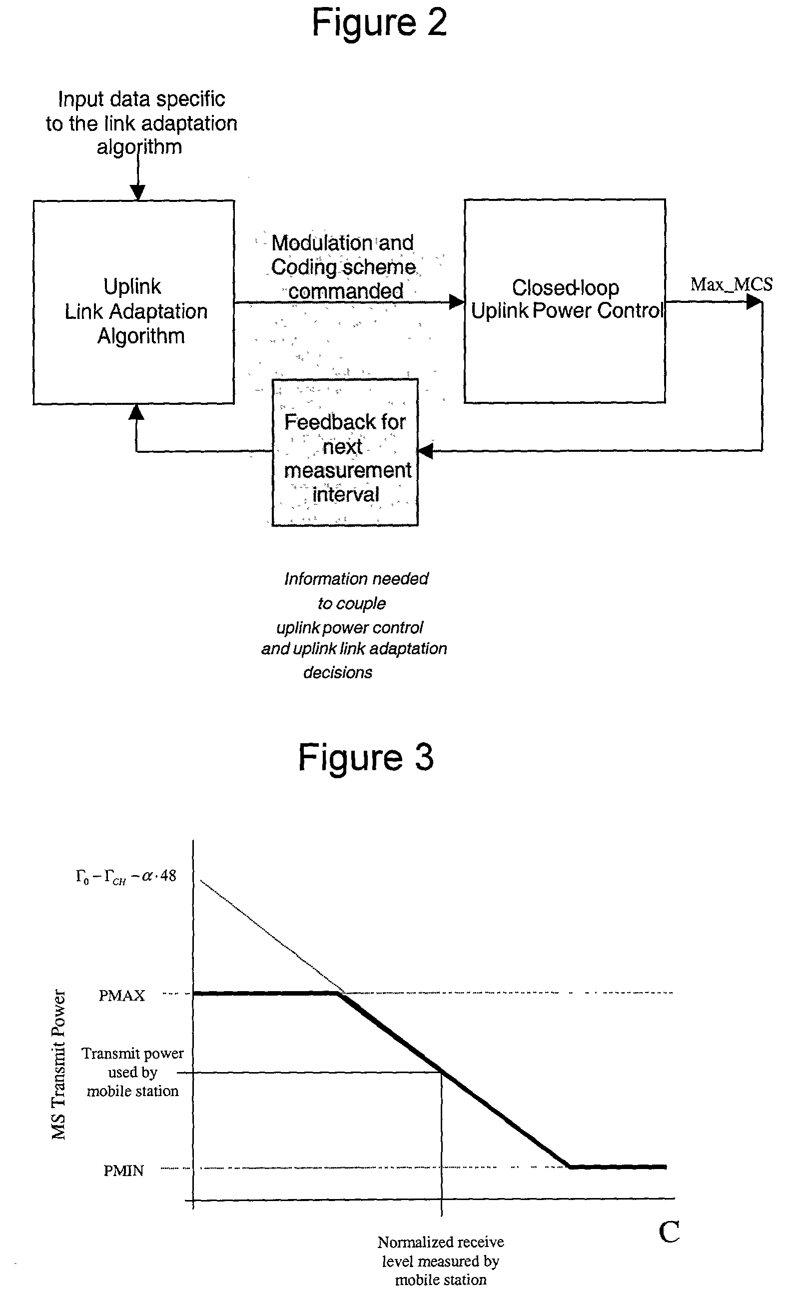
In region C, the higher transmit powers used by the mobile to achieve higher C / I levels at the base transceiver station do not yield substantial increases in LLC throughput.
The additional transmit power, however, generates additional uplink interference to co-channel neighbor cells, and unnecessarily drains the mobile station battery.
But, fast, accurate estimates of C / I levels are difficult to obtain in general.
A power control algorithm attempting to achieve C / I levels adequate for MCS-7, MCS-8 or MCS-9 for mobiles on the fringes of a cell, for example, will likely cause unacceptable levels of interference to co-channel neighbor cells.
For TBFs consisting of only a few uplink blocks, however, this mechanism alone will not result in any reduction in uplink transmit power.
Moreover, data transfer for EGPRS applications may tend to be "bursty", i.e., several packets sent over a relatively short period of time.
TBFs for mobiles running such applications will be short-lived.
Hence, if a TBF for a mobile ends on one TRX, and a subsequent TBF begins on a different TRX, the transmit power used on the old TRX may or may not be sufficient for the new TRX.
For example, in situation where initial transmit power P.sub.0 is much less than target mobile transmit power P.sub.T, then block errors are very likely.

Method used


Image

  • Uplink power control algorithm
  • Uplink power control algorithm
  • Uplink power control algorithm

Examples


Embodiment Construction

of Variables Used in FIG. 9 Explanation of variables used: S.sup.m = set of time slots being used by UL TBF; note that S.sup.m has only one element if TBF is single-slot. S.sub.old.sup.m: this relates to TBF reassignment. We use S.sub.old.sup.m to denote the set of time slots which were being used by the TBF before reassignment. N.sub.tot: used in Quick ACK mode; denotes the total number of RLC blocks received since the TBF was established. k.sub.tot: also used in Quick ACK mode; denotes the total number of RLC blocks Out of N.sub.tot which were received incorrectly. FN.sub.new(s) = all UL RLC blocks received on time slots after FN.sub.new(s) are assumed to have been transmitted using the updated value of .GAMMA..sub.CH(s). Quick_ACK_mode: when set, it denotes that the ULPCA is in the Quick ACK mode. MCS.sub.LA: set to be 2 at the beginning of a TBF. will be the output of the link adaptation algorithm to be used by the power control algorithm during the transmission of a TBF. MAX_MC...


PUM


Abstract

In a system having a base station transmitter for transmitting data blocks to one or more mobile stations over a radio link, there is a method for determining an uplink transmit power level at which to transmit a current data block over a radio link from the mobile to the base transmitter station. The method evaluates airlink quality measurements in the radio link over a measurement interval, wherein each time a message is sent to the mobile station, it is evaluated whether a specified number of uplink blocks have been transmitted by the mobile station since the start of the measurement interval. Based on the evaluated airlink quality measurement, the method determines the uplink transmit power level that the mobile should be using for the current block, and adjusts the transmit power level, if necessary, for the current block.

Description

CROSS REFERENCE TO RELATED CASES[0001] The present invention is related to U.S. patent application Ser. No. 09 / 989,335 of Kenneth C. BUDKA et al., entitled "UPLINK POWER CONTROL ALGORITHM," filed on Nov. 20, 2001, the entire contents of which is incorporated by reference herein.[0002] 1. Field of the Invention[0003] The present, invention relates to wireless communications and, in particular, to a technique for determining uplink power used for transmissions between a base station of a system such as an enhanced general packet radio service (EGPRS) system and one or more mobile stations of the system.[0004] 2. Description of Related Art[0005] A variety of wireless communications systems are increasingly being employed. In cellular systems, for example, a network of base transceiver stations (BTS) is used to provide wireless links with mobile stations or units (e.g., cell phones). The mobile stations, sometimes referred to simply as mobiles, typically communicate via either analog or...

Claims


Application Information

Patent Timeline
IPC IPC(8): H04B7/005H04W52/00H04W52/02H04W52/08H04W52/14H04W52/26
CPCH04W52/08H04W52/146H04W52/265
Inventor BUDKA, KENNETH C.DAS, ARNABZHANG, YINGLU
Owner LUCENT TECH INC
Learn More