Tank having multipe screw-type transfer augers

a transfer auger and multi-pe technology, applied in the field of tanks, can solve the problems of affecting the efficiency of the transfer auger, the single auger is relatively inefficient at moving materials within the tank, and the load is relatively heavy

Inactive Publication Date: 2004-10-21
DEL
View PDF12 Cites 23 Cited by
  • Summary
  • Abstract
  • Description
  • Claims
  • Application Information

AI Technical Summary

Problems solved by technology

So-called shafted augers are relatively heavy, prone to clogging, and are relatively inflexible (that is, are relatively longitudinally rigid).
I. single augers are relatively inefficient at moving materials within the tank, as only a limited portion of the cross-sectional area of the tank can be encompassed by the auger;
III. shafted screw augers are more likely to clog with the common relatively wet and sticky slurries which such tanks contain, and are not as efficient at moving solids / liquids
IV. shafted screw augers are relatively longitudinally stiff, and cannot readily conform to tanks not having a flat bottom; and
In addition, the single speed drive systems of prior art screw auger-equipped tanks are relatively inflexible to accommodate differing environments, particularly different qualities in the solids, liquids, slurries, sludges, etc. that such tanks commonly hold.

Method used


Image

  • Tank having multipe screw-type transfer augers
  • Tank having multipe screw-type transfer augers
  • Tank having multipe screw-type transfer augers

Examples


Embodiment Construction

[0020] While those having ordinary skill in the relevant art field will recognize that changes may be made to the preferred embodiments disclosed in this application, without deviating from the spirit of the invention, with reference to the drawings some of the presently preferred embodiments will be described.

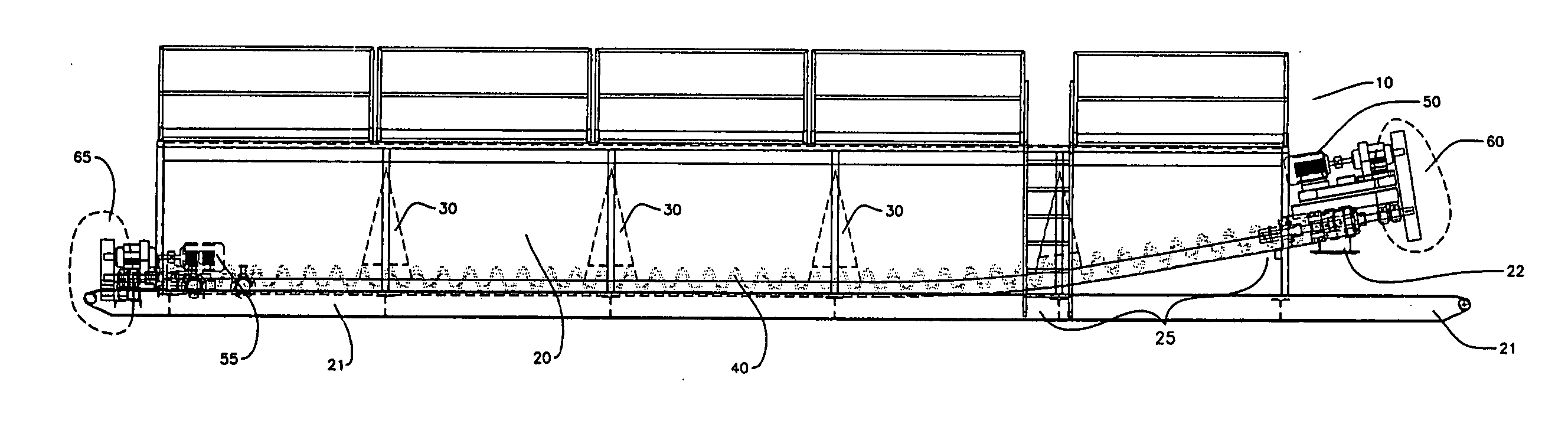
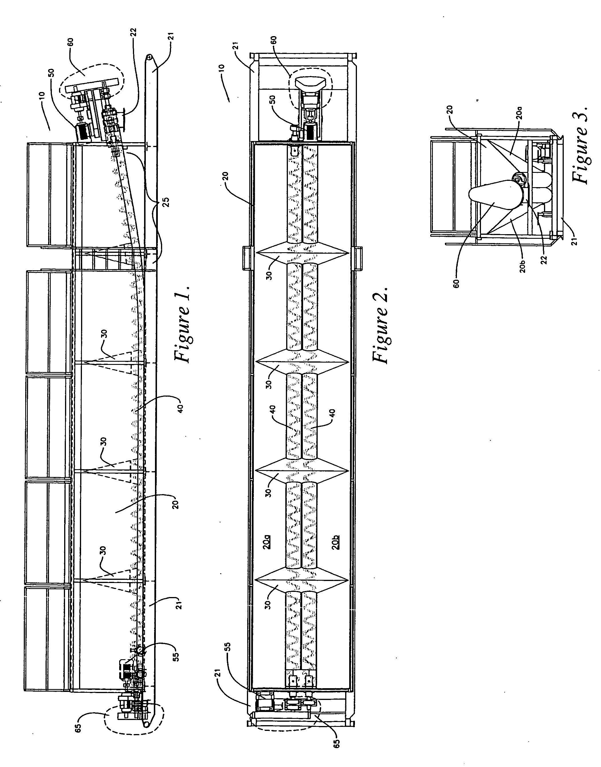
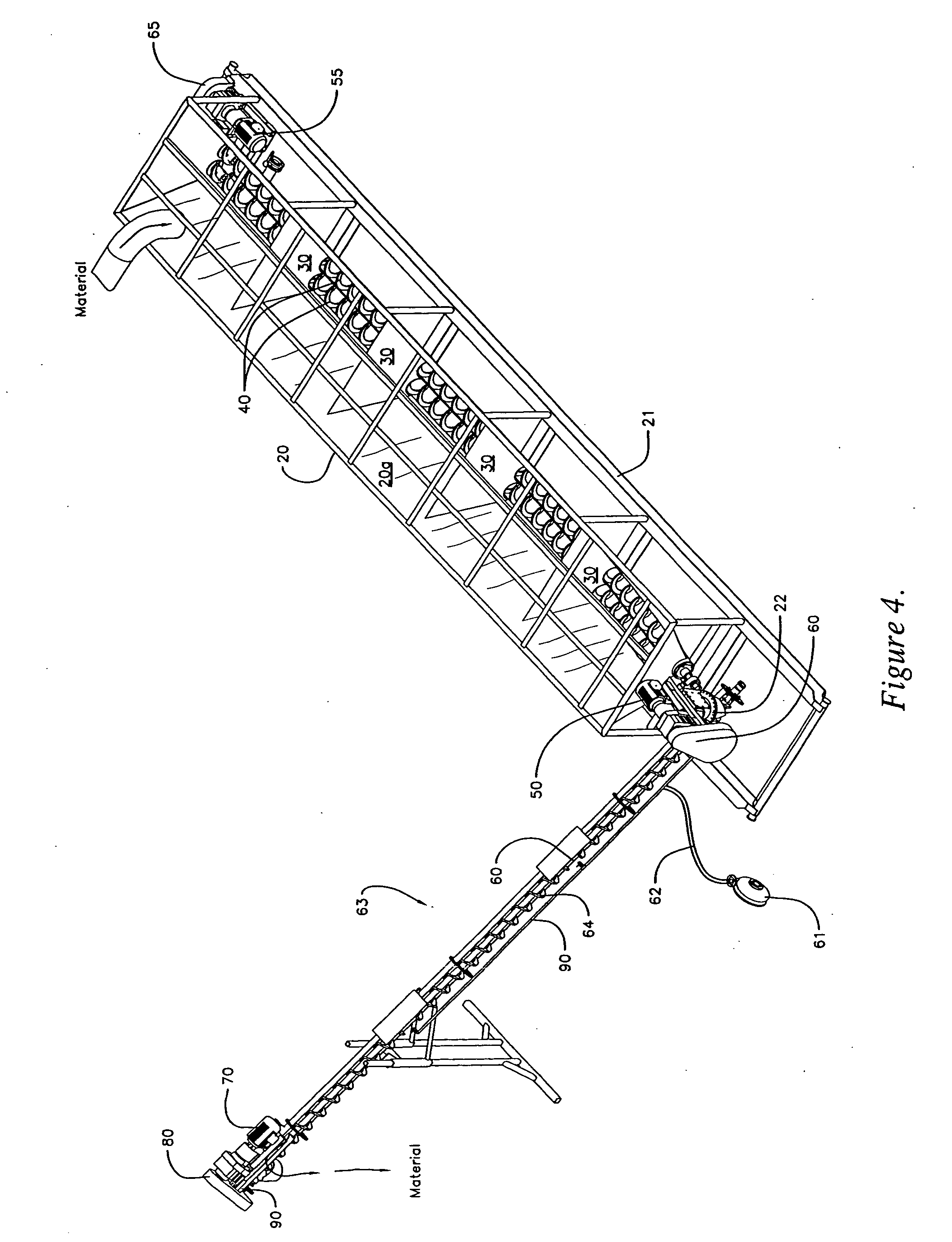
[0021] As shown in FIG. 1, the multiple screw auger tank 10 comprises a generally horizontally elongated tank 20 having opposing sides 20a and 20b, sloping inwardly toward one another from top to bottom. Tank 20, in the presently preferred embodiments, forms generally a V-shape in transverse cross section, with the bottom apex of the "V" somewhat truncated.

[0022] As can be seen particularly in FIGS. 1-3, tank 20 comprises at least one, and preferably two or more, transverse baffles 30, spanning from one side of tank 20 to the other side. In one presently preferred embodiment, baffles 30 extend substantially to the bottom of tank 20, with openings in baffles 30 through which tw...


PUM


Abstract

A multi-screw auger equipped tank comprises opposing sides sloping downward and inwardly toward one another. A plurality of shaftless screw transfer augers run along the tank bottom. Drivers and transmissions coupled to the transfer augers permit simultaneous rotation of the augers in the same or opposite directions of rotation, at the same or different rotational speeds. Materials within the tank, typically slurries or sludges, can be moved to one end of the tank by the transfer augers. An inclined screw auger is disposed near the end of the tank distal from the location at which materials are deposited in the tank. The inclined screw auger picks up the materials and moves them out of the tank. Baffles in the tank aid in dewatering slurries and sludges. Circulation of materials within the tank may be done by rotating the transfer augers in different directions and / or rotational speeds.

Description

[0001] 1. Field of Art[0002] This invention relates to tanks typically used for at least temporary storage and / or processing of solids, liquids, and solid / liquid slurries and sludges of varying degrees of fluidity (from relatively dry to relatively wet), often comprising wellbore drill cuttings, process waste, or other solids. With further specificity, this invention relates to such tanks comprising screw-type augers within the tank, to enable moving materials therein.[0003] 2. Related Art[0004] Tanks having different sizes, cross sectional shapes, and internal baffles or partitions have been used for the collection, holding, and transfer of solid and liquid materials, and mixtures thereof, for many years. These mixtures form slurries and sludges of varying degrees of fluidity. More recently, tanks having some means for moving the material around inside of the tank have been used. One such means is a spiral, screw-type auger, mounted in the tank. Rotation of the auger moves material...

Claims


Application Information

Patent Timeline
Patent Type & Authority Applications(United States)
IPC IPC(8): B65G33/10B65G65/46E21B21/06
CPCB65G33/10B65G65/46E21B21/06
Inventor KULBETH, ROBERT M.
Owner DEL
Why Eureka
Try Eureka