Rotary blowing type powder feeder

A feeder and screw conveyor technology, applied in the field of powder feeders, can solve the problems of reduced pneumatic conveying efficiency, pipeline corrosion, and damaged conveying pipelines, and achieve the effects of improving feeding efficiency, reducing energy consumption, and prolonging the life of pipelines

Inactive Publication Date: 2014-06-25
CHONGQING UNIV
View PDF11 Cites 12 Cited by
  • Summary
  • Abstract
  • Description
  • Claims
  • Application Information

AI Technical Summary

Problems solved by technology

[0005] These classic feeders or feeding systems are all realized by separating quantitative feeding and powder conveying. The structure is complex, and the rotational kinetic energy of the screw auger cannot be fully utilized, which reduces the efficiency of the feeder and causes unnecessary energy loss.
And because the fine particles have a strong inter-particle force, they adhere to each other and coalesce. When they are pneumatically conveyed, they are easy to stick to block the pipe and adhere to the pipe wall, resulting in a decrease in the efficiency of pneumatic conveying. It will cause corrosion to the pipeline, affect the raw material transportation process and damage the transportation pipeline

Method used


Image

  • Rotary blowing type powder feeder

Examples


Embodiment Construction

[0021] The present invention will be described in further detail below in conjunction with the accompanying drawings and specific embodiments.

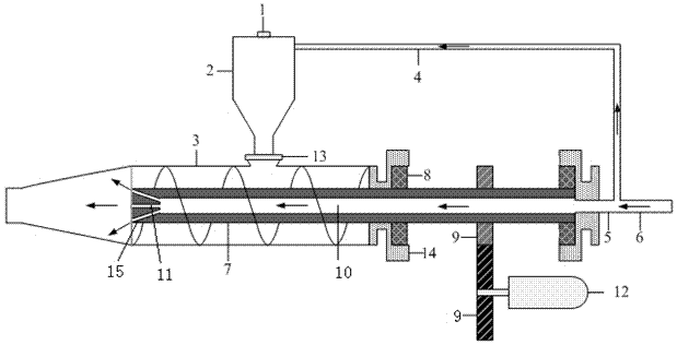
[0022] see figure 1 , the rotary purge type powder feeder of the present invention comprises a silo 2 with a powder inlet and outlet and a screw conveyor housing 3 placed horizontally, the powder inlet 1 is located at the upper part of the silo 2, and the lower end outlet of the silo 2 is connected to the The inner cavities of the screw conveyor housings 3 communicate with each other and a control valve 13 is provided at the connecting position. The front end of the screw conveyor shell is a conical spray area of ​​15°~30°. A screw auger 7 is provided in the screw conveyor housing 3, the tail of the screw auger 7 passes through the screw conveyor housing 3, the end of which is passed out is supported by a bearing 8 and a bearing seat 14, and the end of which is passed through a transmission mechanism at the same time It is connected...


PUM


Abstract

The invention discloses a rotary blowing type powder feeder which comprises a stock bin and a spiral conveyer shell. An outlet in the lower end of the stock bin is communicated with an inner cavity of the spiral conveyer shell, and a spiral auger is arranged in the spiral conveyer shell. The tail of the spiral auger penetrates out of the spiral conveyer shell, and the penetrating-out end of the tail of the spiral auger is connected with a power mechanism through a transmission mechanism. The spiral auger is provided with a central gas channel in the axial direction, the tail of the gas channel is connected with a fan through an air duct, the front end of the spiral auger is provided with a small hole communicated with the gas channel, and the small hole communicates the gas channel with a conical spraying area. The small hole in the front end of the spiral auger rotates along with rotation of a spiral auger shaft, gas sprayed out of the small hole has the automatic rotating blowing effect on the conical spraying area at the front end of the spiral conveyer shell, mineral powder particles, especially viscous fine mineral powder particles are prevented from being aggregated or stuck to the wall, and the powder is continuously conveyed and sprayed in a fluidization mode.

Description

technical field [0001] The invention belongs to a powder feeder, and in particular relates to a feeder which uses a screw auger for forced feeding and uses airflow to rotate and purge for powder conveying, so that it can quantitatively and continuously feed the feeder, which belongs to the powder feeding technology. [0002] Background technique [0003] In the extraction and separation process of mineral resources, it is often necessary to use the method of pneumatic conveying to continuously supply raw materials into the reactor quantitatively and continuously, such as high titanium slag, ultrafine artificial rutile, etc. Due to the strong inter-particle force of fine particles, mutual adhesion and coalescence occur, and when they are pneumatically conveyed, they are easy to stick to block the pipe and adhere to the pipe wall, resulting in a decrease in the efficiency of pneumatic conveying, and some raw materials will also Cause corrosion to the pipeline, affect the raw ...

Claims


Application Information

Patent Timeline
Patent Type & Authority Applications(China)
IPC IPC(8): B65G53/16B65G53/48B65G53/40
Inventor 温良英张正荣梁海龙尹国亮鲁峰涂家佳
Owner CHONGQING UNIV
Why Eureka
Try Eureka