
Angle measuring device and guide

Inactive Publication Date: 2004-11-04
CARPENTERS PAL
View PDF29 Cites 8 Cited by
  • Summary
  • Abstract
  • Description
  • Claims
  • Application Information

AI Technical Summary

Benefits of technology

[0004] It is still another objective of the present invention to provide a multipurpose measuring device which allows the user accuracy and flexibility in measuring angles and linear measurements.
[0007] It is also another objective of the present invention to provide a measuring device which can be accurately pivoted and locked at any angle between zero and ninety degrees (0.degree.-90.degree.).
[0008] It is still another objective of the present invention to provide a guide which can be attached to and used in combination with the measuring device such as when a series of identical angle markings are needed.
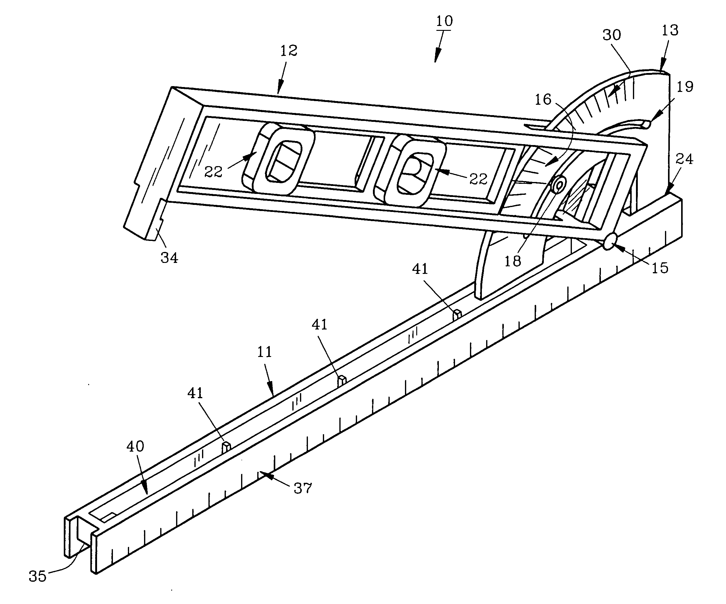
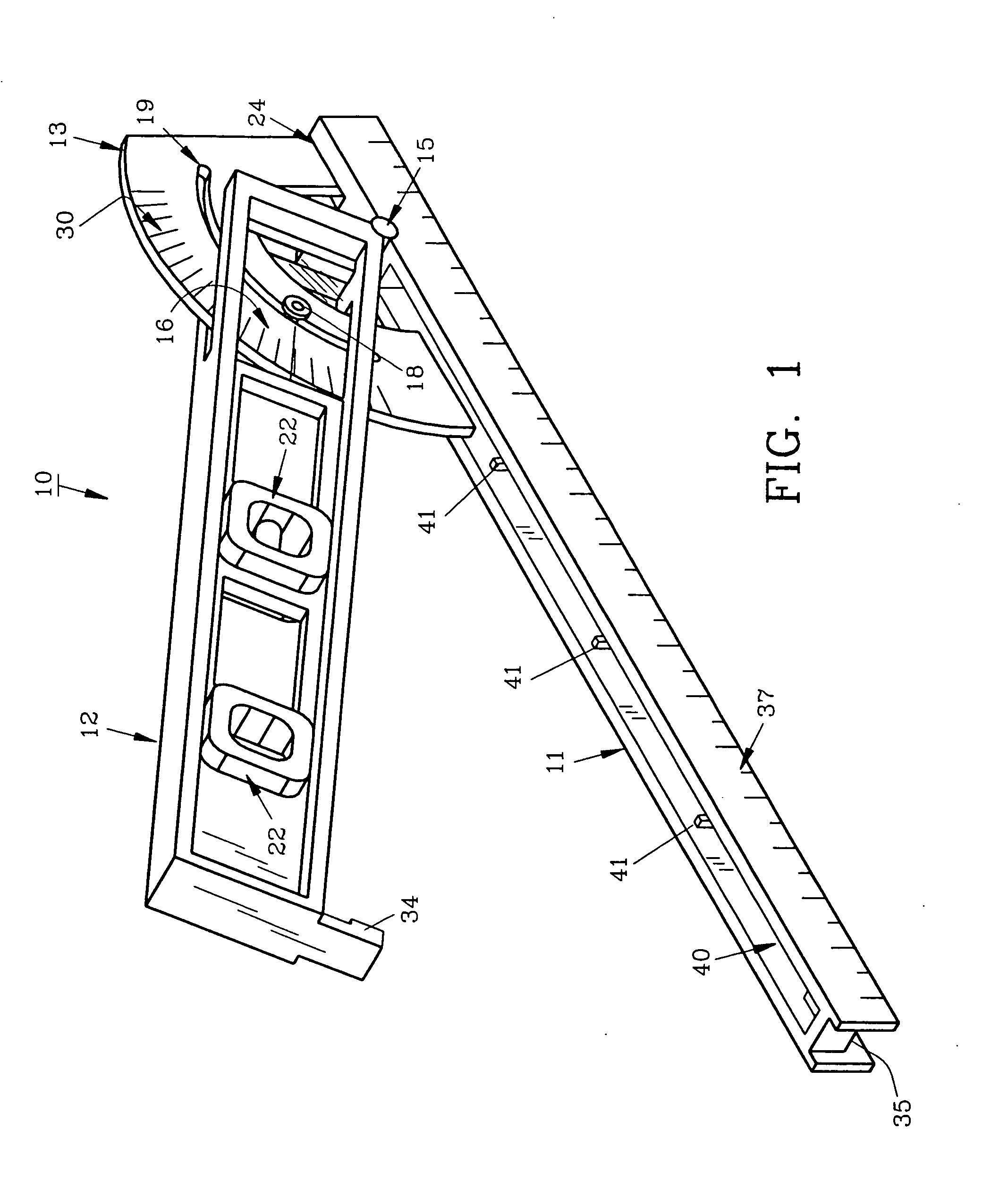
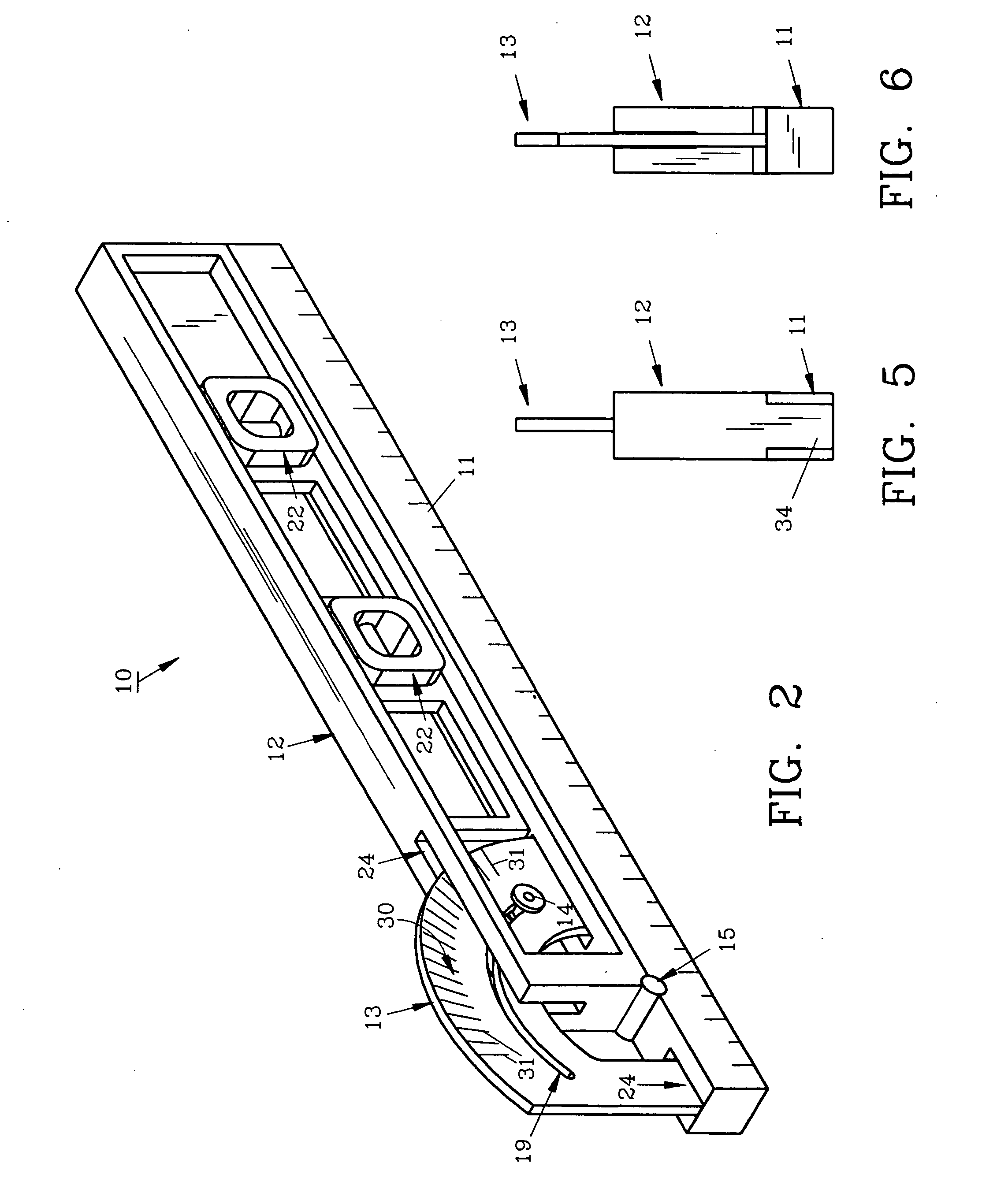
[0012] The invention herein pertains to a measuring device, namely a multipurpose hand tool having a base pivotally affixed to a level. The level includes a rearward slot, proximate its pivot point for containing a protractor whereby the level and base can be pivotally adjusted accurately to any variety of degrees from zero to ninety (0-90) and locked thereat. When the level is pivoted to a ninety degree (90.degree.) angle, the measuring device can be used as a carpenter's square or for other purposes. Uses of the measuring device also include, but are not limited to measuring the pitch of a roof, the grade of a road bed or other surfaces. In addition, a ruler along one side of the base allows the user to take measurements as needed. The preferred length of the base of the measuring device is 15 and {fraction (31 / 32)} inches, thus allowing the tool to be used in setting wall or deck studs on 16 inch centers by providing approximately {fraction (1 / 32)} inch in width for applying a pencil mark.
[0014] A releasable guide is also included which can be adjustably placed on the measuring device. The guide includes a pair of spaced parallel tubular members which are joined at each end by a threaded member which passes through an over sized opening in the longitudinal members. A coiled spring surrounds each threaded member between the longitudinal member and provides resiliency thereto. A knurled nut on each threaded member allows for easy grasping and use. The guide is used in combination with the measuring device by placing it over the pre-opened measuring device and tightening it thereon by turning the knurled nuts. Once in place the combination measuring device and guide can be placed on a wooden board or piece by placing a tubular member of the guide against the edge of the wooden piece as the measuring device rests atop the wooden piece. A pencil or other tool can then be used to mark along the outside of the measuring device to make a pattern, such as a "v" for use as a cutting mark. The combination tool can then be moved along the wooden piece and the "v" pattern repeated as needed. This method enables the user to produce uniform and precise measurement markings for cutting purposes such as required in making a stair stringer or other building component.

Problems solved by technology

Tools and devices in recent years have greatly increased in complexity and price.
However, many multipurpose tools available today are bulky and inconvenient to handle.
Some multipurpose tools provide several particular uses, but certain of these uses are very rarely needed, making them relatively expensive and providing little convenience.

Method used


Image

  • Angle measuring device and guide
  • Angle measuring device and guide
  • Angle measuring device and guide

Examples


Embodiment Construction

[0031] For a better understanding of the invention and its operation, turning now to the drawings, FIG. 1 demonstrates preferred measuring device 10 seen in perspective fashion having base 11, level 12 and protractor 13. As shown in FIGS. 1, 2, and 7, slot 24 is defined by level 12 to accommodate protractor 13. Protractor 13 is rigidly mounted within base 11 such as by pins, frictionally fitting therein or with conventional glues or adhesives. Level 12 is also mounted to base 11 by hinge 15. Window 16 within level 12 is preferably formed from a transparent rigid plastic material such as a clear polycarbonate or polyacrylate and is affixed to level 12 as seen in FIGS. 1, 3, and 4. Window 16 includes aperture 17 through which threaded locking member 18 is positioned. Locking member 18 passes through window aperture 17 of window 16 and slot 19 of protractor 13 whereby, effectively bolt nut 14, as seen in FIG. 2, is used to tighten threaded member 18 in place. Locking member 18 can be m...


PUM


Abstract

A measuring device is provided for carpenters, roofers and other tradesmen. The device is made of relatively lightweight plastic and has a variety of uses. The elongated base is rectangular in cross-section and includes a scale for measuring distances along one side. Pivotally affixed to the base is a level which can be locked against a protractor (also affixed to the base) at any angle between zero and ninety degrees (0°-90°). Roof pitches, gradients and other angles can be determined or set in a simple, easy to learn manner. In addition, a guide is provided which can be releasably attached to the measuring device for use in combination therewith for precise repeated markings on lumber pieces or boards for forming stair stringers and the like.

Description

[0001] This is a continuation-in-part of and claims benefits under pending patent application Ser. No. 10 / 427,002 filed 01 May 2003, now U.S. Pat. No. ______.[0002] The invention herein pertains to a measuring device for use by carpenters and other tradesmen for measuring and setting angles and pitches and for marking cutting patterns.DESCRIPTION OF THE PRIOR ART AND OBJECTIVES OF THE INVENTION[0003] Tools and devices in recent years have greatly increased in complexity and price. Tools which have multiple purposes are becoming increasingly popular since a tradesman can more easily purchase and transport a single tool instead of two or three tools each having a single purpose. However, many multipurpose tools available today are bulky and inconvenient to handle. Some multipurpose tools provide several particular uses, but certain of these uses are very rarely needed, making them relatively expensive and providing little convenience. The measuring device can also be used in combinati...

Claims


Application Information

Patent Timeline
IPC IPC(8): G01B3/56G01C9/28
CPCG01B3/563G01C9/28
Inventor ELLIS, MERLE R.HALEY,, CLARENCE W. JR.
Owner CARPENTERS PAL
Learn More