

Large effective area high SBS threshold optical fiber
a high-sbs threshold, optical fiber technology, applied in the direction of cladded optical fiber, optical elements, instruments, etc., can solve the problems of nonlinear penalty, inability to reflect back undetected large amount of signal power, and stimulated brillouin scattering (sbs)
- Summary
- Abstract
- Description
- Claims
- Application Information
AI Technical Summary
Benefits of technology
Problems solved by technology
Method used
Image

Examples
Embodiment Construction
, made via an outside vapor deposition (OVD) process.
4 TABLE 3 Example: Ex 8 Ex 9 Length km 24.0 24.0 Attenuation at 1310 nm dB / km 0.326 0.328 Attenuation at 1380 nm dB / km 0.319 0.320 Attenuation at 1550 nm dB / km 0.190 0.191 2 m Fiber Cutoff nm 1412 1379 Wavelength Cabled Cutoff nm 1273 1246 Wavelength AOEA.sub.L01 .mu.m.sup.2 235 235 AOEA.sub.L02 .mu.m.sup.2 266 266 Ratio: AOEA.sub.L01 / 0.88 0.88 AOEA.sub.L02 A.sub.eff at 1550 nm .mu.m.sup.2 103 101 MFD at 1550 nm .mu.m 11.52 11.4 Zero Dispersion nm 1310 1308 Wavelength Dispersion at 1310 nm ps / nm-km -0.014 0.062 Dispersion at 1550 nm ps / nm-km 18.0 18.1 Dispersion at 1625 nm ps / nm-km 22.5 22.6 Dispersion Slope at 1550 nm ps / nm.sup.2-km 0.062 0.063 Kappa nm 290 287 PMD ps / sqrt(km) 0.019 0.016 Pin Array at 1550 nm dB 2.1 3.4 Pin Array at 1620 nm dB 3.1 5.2 20 mm dia Macrobend dB / turn 0.73 0.58
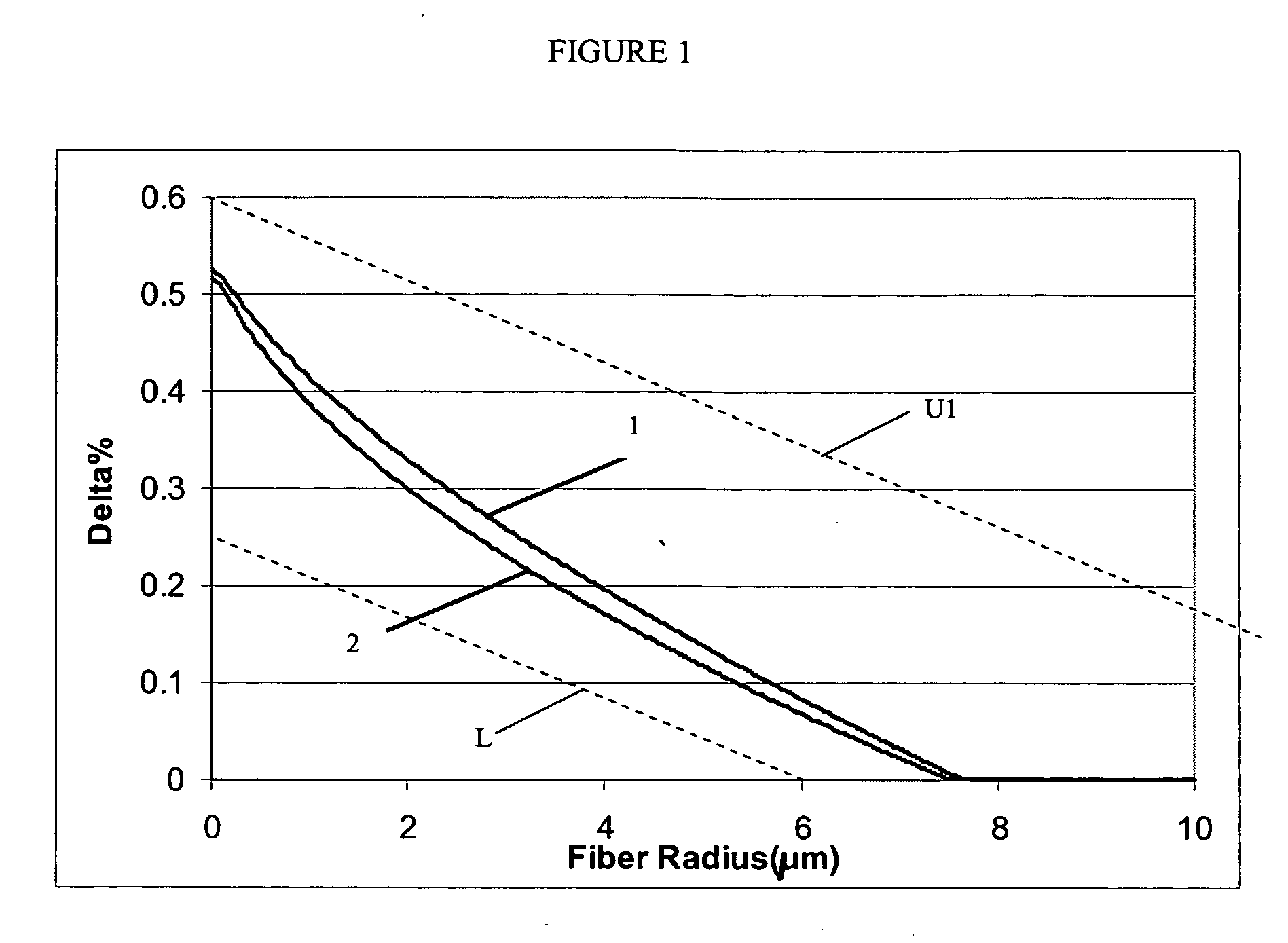
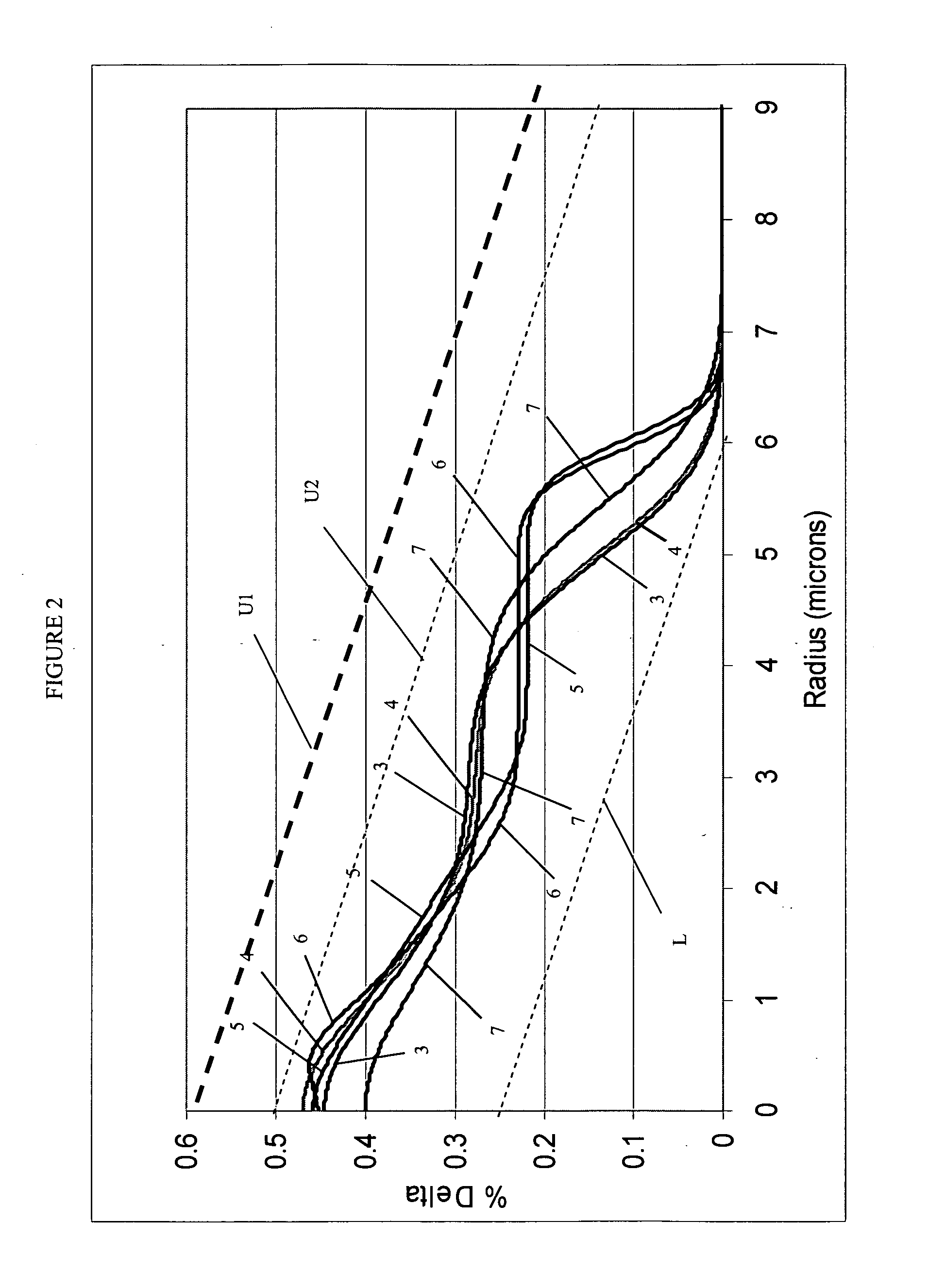
[0126] The relative refractive index profiles of Examples 8-9 were substantially similar to the profile described in Example 5 above and as rep...
PUM
 Abstract
Description
Claims
Application Information