Method and apparatus for distributing treatment agents

a technology of treatment agent and treatment agent, applied in the field of treatment agent delivery system, can solve the problems of negating the purpose of providing such an apparatus, reducing the effect of treatment agent degradation over long periods of time, and reducing the potential for treatment agent degradation

Inactive Publication Date: 2004-11-04
AMBERLEY MANAGEMENT SERVICES
View PDF3 Cites 34 Cited by
  • Summary
  • Abstract
  • Description
  • Claims
  • Application Information

AI Technical Summary

Benefits of technology

0056] The present invention provides many potential advantages over prior art delivery systems.
0057] By eliminating the need for a large container of treatment agent this in turn eliminates the insect's opportunity to rob the source of treatment agent and return immediately to a beehive or other similar insect colony. By spraying treatment agents, insects are not necessarily aware that they are walking over or through material which they would normally gather from vegetation and will therefore still travel out into the nearby or surrounding vegetation and distribute the treatment agent.
0058] Furthermore, the present invention may also be adapted to provide or form part of a combined entrance and exit to an insect colony (preferably a beehive). Therefore installation of the present invention does not necessarily require that the insects of the colony learn the location of both an exit and entrance point, thereby eliminating the problems associated with this activity.
0059] By regularly spraying small amounts of treatment agent, the potential for treatment agent degradation over long periods of time is reduced. As only small amounts of agent are delivered at one time the bulk of the treatment agents to be delivered are protected until required.

Problems solved by technology

However, there are some problems with the design and use of such systems.
This negates the purpose of providing such an apparatus as the bee does not come into contact with the crop to be pollinated.
However, the provision of a separate entrance and exit to a hive can cause substantial confusion to the bee population, as bees need a significant amount of time to recognise that the entrance and exit of the hive are at separate locations.
In addition, a further drawback with these systems arises as a consequence of providing a large container or trough of treatment agent, as the apparatus need only be attended infrequently.
Thus, as a large trough of agent can be left for long periods within the apparatus, through exposure to air and water the treatment agent can experience a loss in viability or potency over time.

Method used


Image

  • Method and apparatus for distributing treatment agents
  • Method and apparatus for distributing treatment agents
  • Method and apparatus for distributing treatment agents

Examples


Embodiment Construction

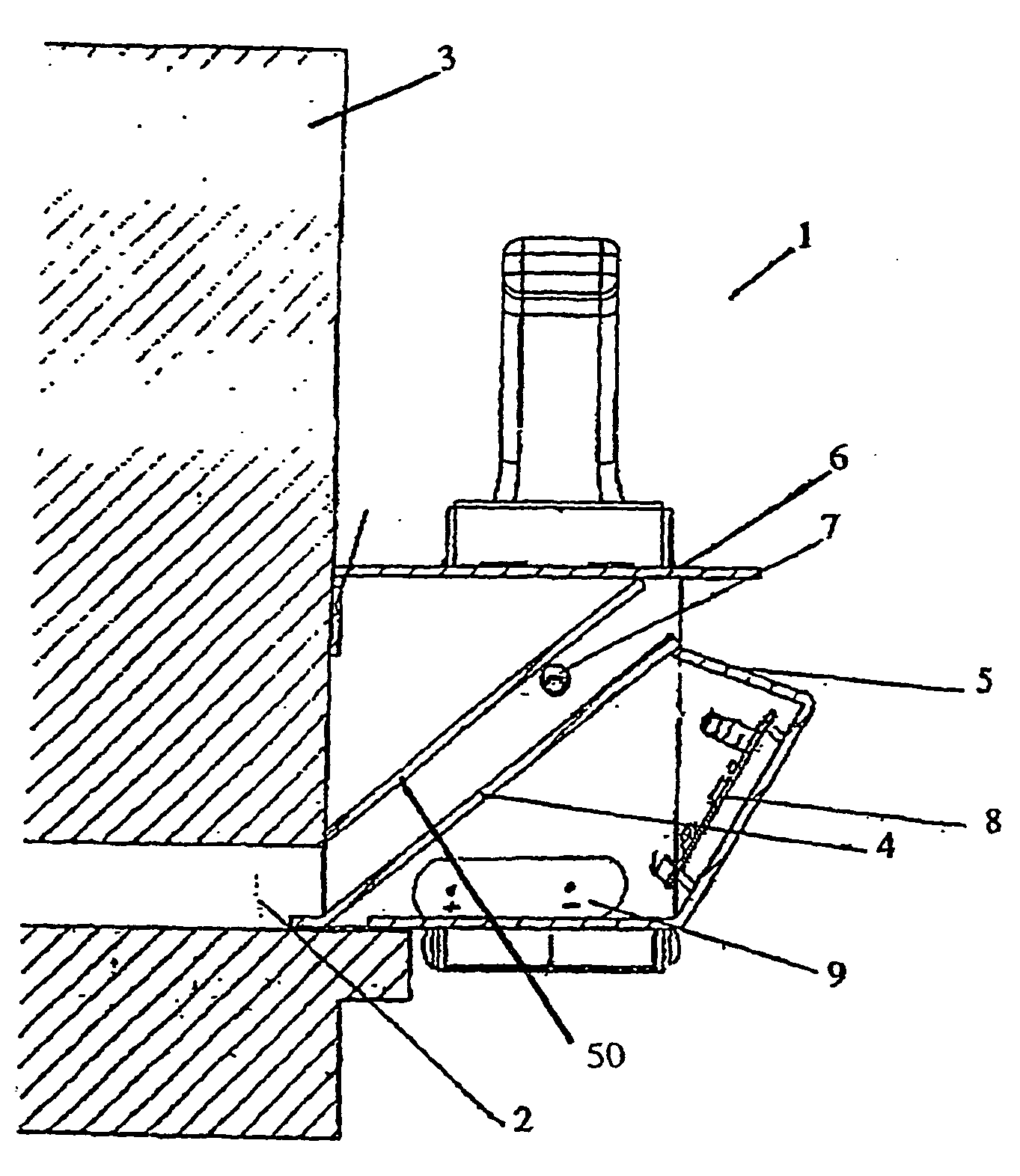
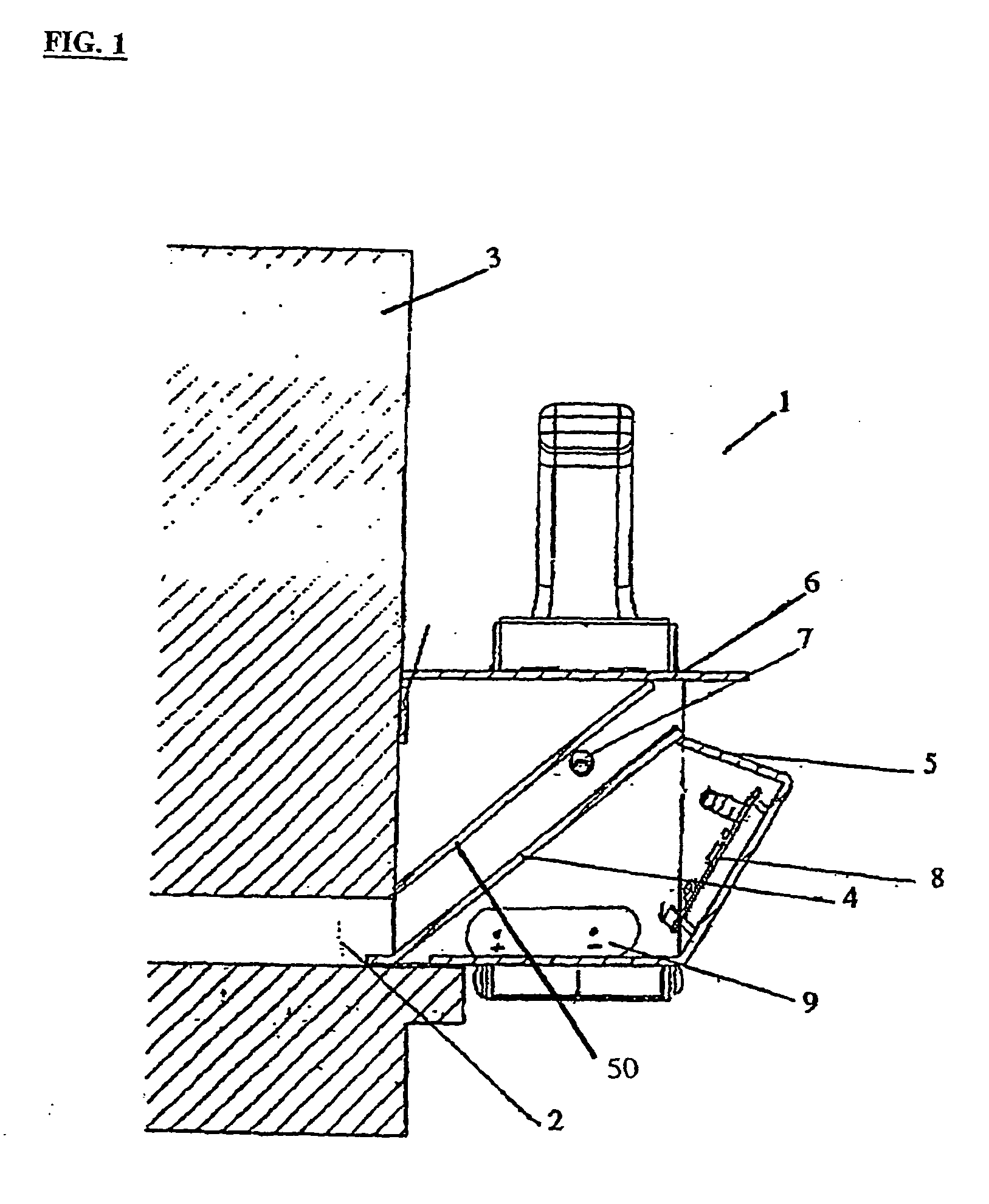
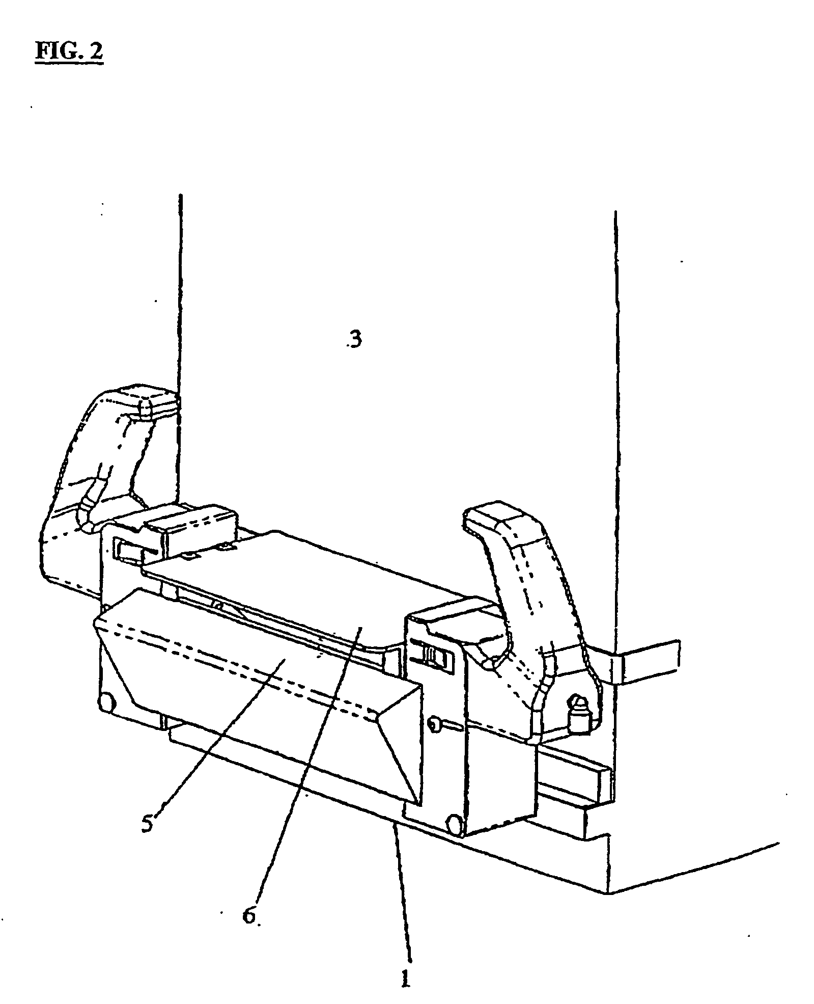
[0064] FIGS. 1 and 2 show side cross section and perspective views of a treatment agent delivery system or device 1 formed in accordance with a preferred embodiment of the present invention. In the embodiment shown the system 1 is connected to the combined entrance and exit 2 of the beehive 3. In this instance the insect travel route which the inventions is placed in close proximity to is formed by the hive entrance and exit 2.

[0065] The system 1 employs a single distribution surface in the form of a distribution ramp 4. Bees wishing to exit the hive 3 must walk up the ramp and bees entering the hive must walk down the ramp. The upper portions of the ramp 4 are associated with the landing pad 5 for bees approaching the hive and also a roofing element 6 which is formed to prevent rain coming into contact with the surface of the ramp 4. The upper surface 50 of the ramp 4 can also form an additional distribution surface for any bees that decide to walk along this surface to enter / exit ...


PUM


Abstract

A treatment agent delivery system which includes at least one distribution surface adapted to be located in close proximity to an insect travel route and a spray delivery system including a nozzle, electronic controls and a battery, with the spray delivery system adapted to spray at least one treatment agent onto said distribution surface.

Description

[0001] This invention relates to a method and apparatus for distributing treatment agents to vegetation. Preferably the invention uses bees or other insects to distribute the treatment agents to vegetation through such agents being sprayed onto a surface which the bees or insects pass regularly, such as the exit to a beehive. For use of reference only throughout the specification, will refer to bees being employed to spread treatment agents and the apparatus associated with the present invention being located on or within a beehive. However, those skilled in the art should appreciate that other insects may also be used to distribute treatment agents without departing from the scope of the present invention.[0002] In many instances it is desirable to apply a treatment agent or agents to a vegetative crop. Previously, for example, bees have been employed to distribute treatment agents to crops as they visit flowers to collect nectar and pollen. Good examples of systems that exploit th...

Claims


Application Information

Patent Timeline
Patent Type & Authority Applications(United States)
IPC IPC(8): A01K47/00A01G7/00A01M7/00A01N25/00A01N25/06
CPCA01G7/00A01K47/06A01M7/00
Inventor WILLACY, GEOFFREY VALENTINE
Owner AMBERLEY MANAGEMENT SERVICES
Why Eureka
Try Eureka