Sliding bed

a bed and sliding technology, applied in the field of sliding beds, can solve the problems of inability to lower the feet from the bed and assume, the patient cannot get up by himself, and the disadvantage of not being able to assume a state similar to sitting in a chair

Inactive Publication Date: 2004-11-18
NOMURA KYOZO
View PDF1 Cites 36 Cited by
  • Summary
  • Abstract
  • Description
  • Claims
  • Application Information

AI Technical Summary

Benefits of technology

[0076] As described above, a sliding bed according to the present invention has a configuration in which both sides of a movable bed frame are caused to slide using two or more slide parts, thereby allowing movement to commence with that slide part having the least resistance to sliding. For this reason, during slide commencement, when much force is usually needed, movement can be effected using relatively small force.[0077] A sliding bed according to the present invention is stable even when the height is adjusted, and the height can be freely adjusted; therefore, when a patient on a sliding bed is transferred to a wheelchair or portable toilet, the height of the sliding bed can be adjusted to be slightly higher than the wheelchair or portable toilet, and the patient can be transferred to the wheelchair or the like without being carried, by making use of this difference in height, resulting in far greater efficiency in care-giving tasks.[0078] Further, because the tipping-over prevention member and slide parts are formed unitarily, height adjustment of the bed is easy. Further, by providing a tipping-over prevention member or a balance weight on the side of the bed base opposite the side to which sliding is made, the tipping over of a sliding bed can be more safely assured.[0079] Further, by providing a moving balance weight that moves to the opposite side in concert with the sliding movement of the movable bed frame, the sliding bed can be slid in either direction, resulting in a significant expansion of uses for the bed.

Problems solved by technology

With just this art, however, a patient cannot get up by himself, nor can he lower his feet from the bed and assume a position as of sitting in a chair.
Therefore, this is disadvantageous when considered from the perspective of patient treatment or rehabilitation, as the circulation of the bodily fluids throughout the entire body and the use of muscles throughout the body are far lower than for a healthy person; in addition, being unable to assume a state similar to sitting in a chair is disadvantageous when considered from the point of view of relieving stress and improving the psychological state of a patient.
Further, because individual patients will have different body sizes, with the lengths of patients' legs in particular varying from individual to individual, it is difficult to adjust bed height to match individual patients.
Further, as in the art disclosed in Japanese Utility Model Registration #3038378 and Japanese Laid-open Patent Application 2000-042053, in cases of a configuration where a sliding portion is not supported by leg members, but support members are provided extending directly from the frame of the bed main body, the load on the sliding portion is centered on the bed end part on the slide side of the movement mechanism, and when a patient is placed thereupon, it is heavy and difficult to move.
In addition, a bed used by patients needs to be disinfected or otherwise sterilized periodically, and a metal slide mechanism used in a slide bed can easily suffer from rusting or other such corrosion.
This becomes somewhat heavy.
For this reason, when one attempts to slide the movable bed frame 3 to a standard state, it becomes extremely heavy.
The reason for providing cutaway shapes in such a manner is, when the bed is made to slide, the resistance of flexible mats is large, and the force needed for causing sliding becomes large.

Method used


Image

  • Sliding bed
  • Sliding bed
  • Sliding bed

Examples


Embodiment Construction

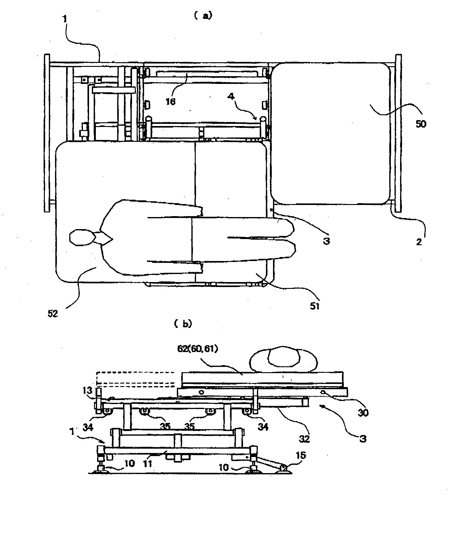
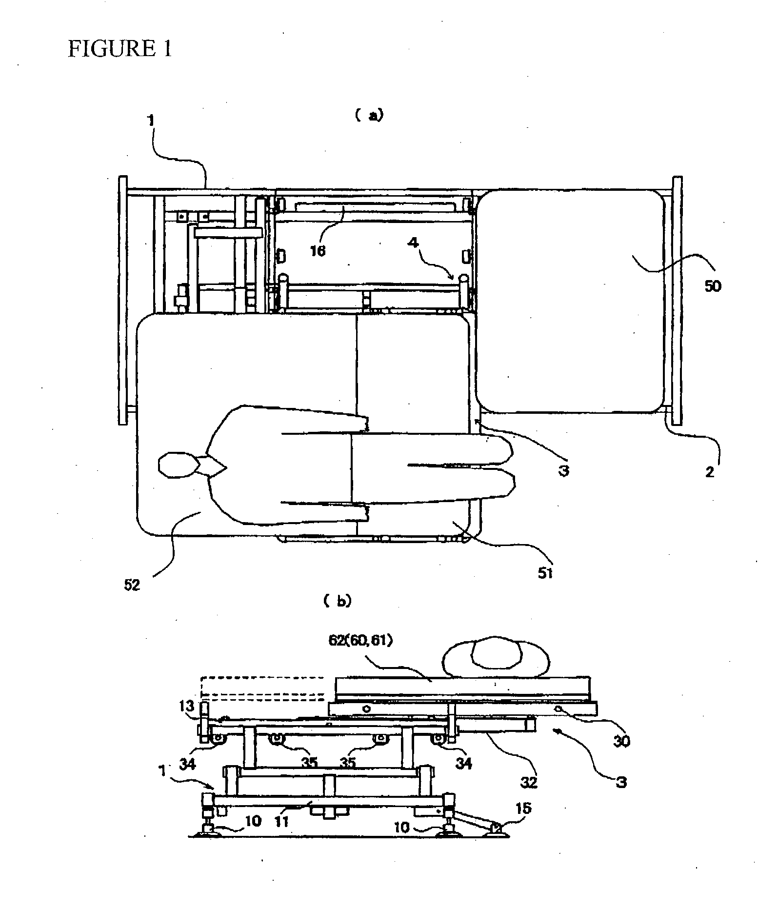
[0073] Next, in the embodiment shown in FIGS. 9 to 12, the balance weight 16 described above is not fixed to the bed, but moves in accordance with slide amount.

[0074] Thus the intermediate slide frame 32 and a moving balance weight 70 capable of moving along a moving guard rail are connected by a wire 72 that changes direction by means of a wire sheave 71 provided on the upper frame 13 (or fixed bed frame 2). Therefore, as shown in FIG. 11, when the upper slide frame 30 is moved from the state shown in FIG. 10 to the right side, the intermediate slide frame 32, in accordance with the sliding of the movable bed frame 3, moves in the opposite direction of the movable bed frame 3 slide direction, by means of the wire 72, operating to offset the movement of the center of gravity of the movable bed frame 3. Therefore, the movable bed frame 3 can be pulled in either direction, increasing the range of use of the sliding bed.

[0075] It should be noted that while the above-described moving we...


PUM


Abstract

To devise a slide mechanism and to provide a sliding bed that is configured to be easy to slide and the height of which is freely adjustable, so as to lessen the burden on a care-giver, a sliding bed includes a bed base 1, a fixed bed frame 2 provided on the bed base 1, a movable bed frame 3 capable of moving in the widthwise direction of the bed base, and a seat and back rest on the movable bed frame 2, the back rest being capable of being raised either electrically or manually; the movable bed frame 3 is supported so as to capable of moving in the widthwise direction of the bed base 1 by at least two slide parts 4 provided on each of the two sides of the movable bed frame 3.

Description

[0001] 1. Field of the Invention[0002] The present invention relates to a sliding bed used in the care or nursing of the elderly or disabled (hereinafter, "patient") and designed so as to lessen the burden of a patient in a hospital or the like when getting into or out of a bed, or to lessen the burden of a caregiver for such patient.[0003] 2. Description of the Related Art[0004] In conventional nursing beds for the disabled, the predominant art involves the raising up of the upper body of a patient. With just this art, however, a patient cannot get up by himself, nor can he lower his feet from the bed and assume a position as of sitting in a chair. Therefore, this is disadvantageous when considered from the perspective of patient treatment or rehabilitation, as the circulation of the bodily fluids throughout the entire body and the use of muscles throughout the body are far lower than for a healthy person; in addition, being unable to assume a state similar to sitting in a chair is...

Claims


Application Information

Patent Timeline
Patent Type & Authority Applications(United States)
IPC IPC(8): A61G7/012A61G7/053A61G7/10A61G7/16
CPCA61G7/012A61G7/053A61G7/1034A61G7/1067A61G7/16
Inventor NOMURA, KYOZO
Owner NOMURA KYOZO
Why Eureka
Try Eureka