Wire fault detection

a fault detection and wire technology, applied in the field of diagnostics, can solve problems such as undetected defects, difficult to detect and diagnose existing wiring systems,

Inactive Publication Date: 2004-11-18
SIMMONDS PRECISION PRODS
View PDF17 Cites 62 Cited by
  • Summary
  • Abstract
  • Description
  • Claims
  • Application Information

AI Technical Summary

Problems solved by technology

Existing wiring systems may experience problems that are difficult to detect and diagnose.
However, defects may go u

Method used


Image

  • Wire fault detection
  • Wire fault detection
  • Wire fault detection

Examples


Embodiment Construction

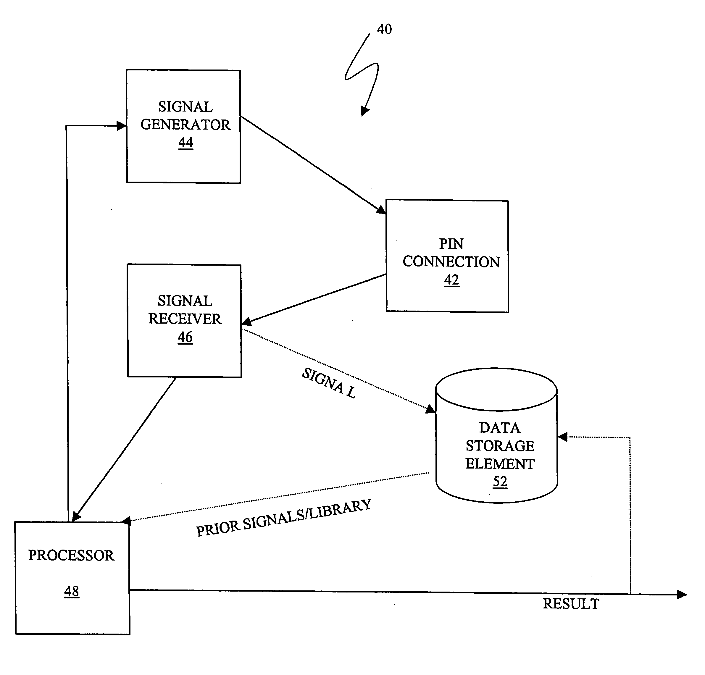
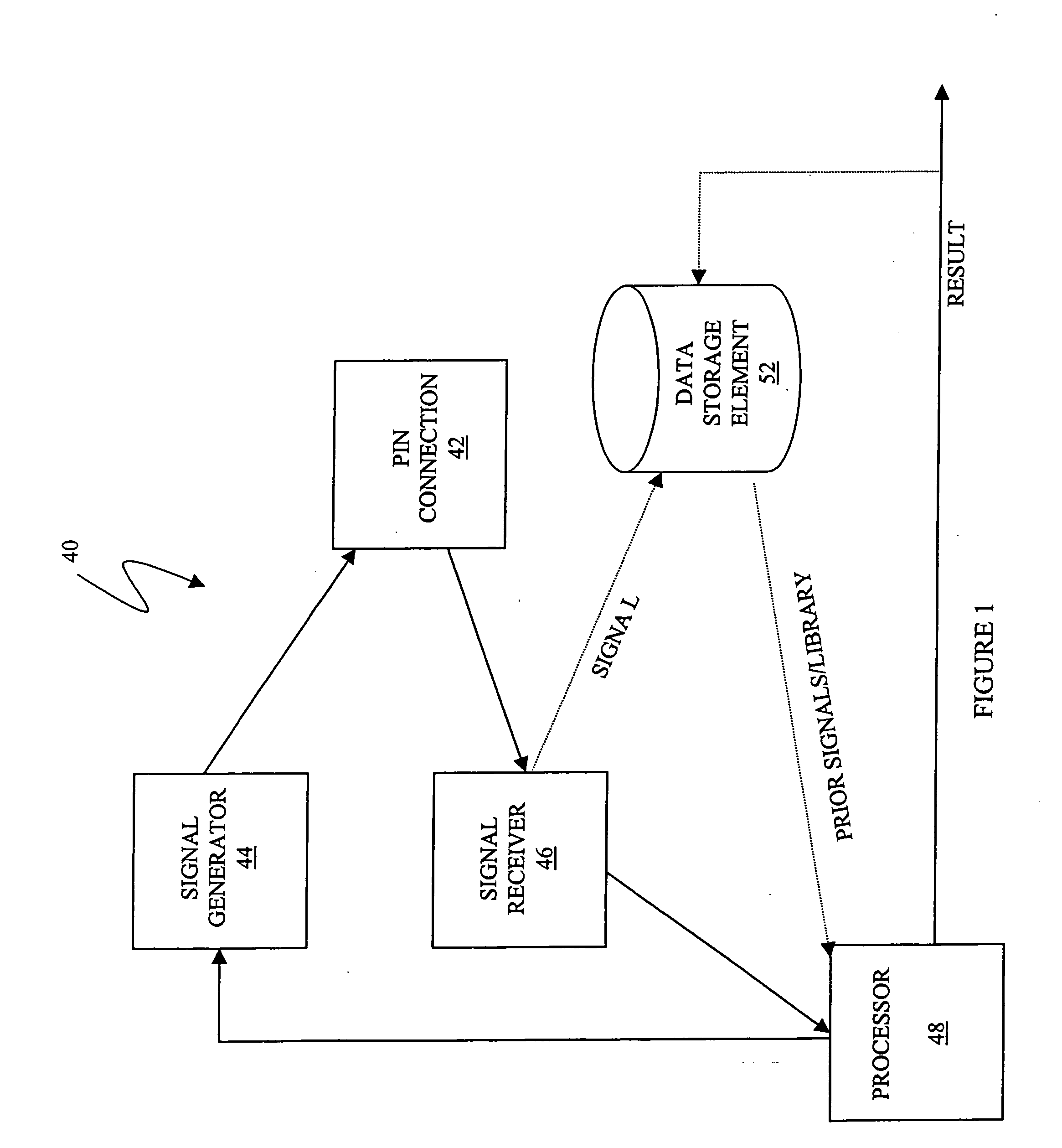
[0073] Referring to FIG. 1, shown is a system 40 that performs wire diagnostics. The system 40 includes a pin connection 42 that couples to one or more pins of a wire that may be part of a wiring harness. The pin connection 42 may connect to a single pin or may connect to multiple pins. In some instances (described elsewhere herein), a signal is generated and provided on a first pin and signal is received on a second, different pin. In other embodiments, a signal is generated on a pin and a signal is measured on the same pin. The sent and received signals are provided through the pin connection 42.

[0074] A signal generator 44 is coupled to the pin connection 42 and provides a signal thereto. In some embodiments, the signal generator 44 may provide a square pulse or step function pulse. In other embodiments, the signal generator 44 may provide a swept frequency signal or may provide a sine wave at a particular frequency or at a particular set of frequencies. Much, if not all, of the ...


PUM


Abstract

Described are techniques used in a wire diagnostics system to detect events, such as defects, that may occur within a wire or cable under test. An incident voltage signal is sent out on the wire and a measured voltage signal is obtained which includes the incident voltage and the reflected voltage. Compensation processing is performed on the measured waveform to remove unwanted reflective components. Additionally, the waveform is then subject to attenuation processing and event detection processing. Detected events, such as defects, are classified and output as results. Events are classified by parametric classification using a library of known events or faults. The library of known events or faults is previously generated using empirical analysis and modeling techniques. Additionally, joint time-frequency domain reflectometry (TFDR) techniques are described for event identification and classification for a wire under test.

Description

[0001] 1. Technical Field[0002] This application relates to the field of diagnostics, and more particularly to the field of diagnostics that determine the condition of cables and wires.[0003] 2. Description of Related Art[0004] Wiring systems may be used in a variety of industries, such as the aviation and aircraft industry. Different devices and components may be controlled, monitored and / or enabled using the wiring systems. Existing wiring systems may experience problems that are difficult to detect and diagnose.[0005] One existing technique is detection of problems through visual inspections, for example, as in connection with general procedures and inspections of aircraft wiring systems. However, defects may go undetected and may only be detected after a system failure or after a more noticeable amount of damage has occurred.[0006] It may be desirable for a variety of different reasons, including safety considerations, to provide an efficient and effective technique that may be ...

Claims


Application Information

Patent Timeline
IPC IPC(8): G01R31/00G01R31/08G01R31/311
CPCG01R31/008G01R31/088G01R31/11
Inventor BECHHOEFER, ERIC ROBERTSADOK, MOKHTAR
Owner SIMMONDS PRECISION PRODS
Why Eureka
Try Eureka