Method and apparatus for blind source separation using two sensors

a technology of two sensors and source separation, applied in the field of blind source separation, can solve the problems of noise elimination performance greatly deterioration, signal separation performance greatly deterioration, performance of the mobile sound input system, etc., and achieve the effect of removing noise from the received signal

Active Publication Date: 2004-11-18
SAMSUNG ELECTRONICS CO LTD
View PDF1 Cites 56 Cited by
  • Summary
  • Abstract
  • Description
  • Claims
  • Application Information

AI Technical Summary

Benefits of technology

0010] The present invention provides a method of separating mixture signals received through t...

Problems solved by technology

Important issues affecting the performance of the sound input system of the mobile robot are factors such as noises, reverberations, and distances to an operator in an indoor environment.
However, when the reference microphone receives other noise rather than only the predetermine noise, the noise elimination performance is greatly deteriorated.
2677-2684, 1999, is disadvantageous in that a voice activity detector is required...

Method used


Image

  • Method and apparatus for blind source separation using two sensors
  • Method and apparatus for blind source separation using two sensors
  • Method and apparatus for blind source separation using two sensors

Examples


first embodiment

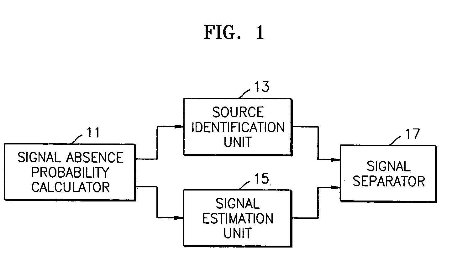
[0036] FIG. 1 is a block diagram of a signal separation apparatus according to the present invention. The signal separation apparatus comprises a signal absence probability calculator 11, a source identification unit 13, a signal estimation unit 15, and a source signal separator 17. The signal separation apparatus separates N independent sources from M microphone observations, where M.ltoreq.N. Hereinafter, for convenience of description, an exemplary case when M=2 will be described.

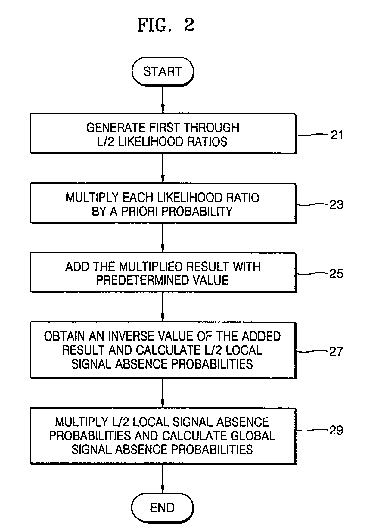
[0037] Referring to FIG. 1, the signal absence probability calculator 11 calculates a global signal absence probability p(H.sub.0.vertline.X(m)) and a local signal absence probability p(H.sub.0,k.vertline.Xk(m)) for each of the frequency bins of an m-th frame, for one of the first and second microphone observations which are received through two sensors, for example, two microphones, and are transformed into frequency-domain signals. Referring to FIG. 2, this calculation is described in more detail as fo...

second embodiment

[0095] FIG. 7 is a block diagram of a signal separation apparatus according to the present invention, wherein the source separation apparatus comprises a signal absence probability calculator 71, a signal estimation unit 73, a source identification unit 75, and a source signal separator 77.

[0096] Referring to FIG. 7, the signal absence probability calculator 71 calculates the global signal absence probabilities p(Ho.vertline.X1(m)) and p(Ho.vertline.X2(m)) for the m-th frame and the local signal absence probabilities p(Ho,k.vertline.X1,k(m)) and p(Ho,k.vertline.X2,k(m)) at each of frequency bins of the m-th frame, for the first and second microphone observations X1(m) and X2(m).

[0097] The signal estimation unit 73 estimates a spectrum vector in which noise signals are eliminated for each frequency band per frames using the global signal absence probabilities calculated by the signal absence probability calculator 71, for the first and second microphone observations, and generates fi...


PUM


Abstract

A method and apparatus to separate first and second mixture signals received from two sensors and transformed into the frequency domain in two or more source signals. The signal separation method includes: calculating a global signal absence probability for each frame and a local signal absence probability for each frequency band of a corresponding frame for at least one of the first and second mixture signals; estimating a spectrum vector for each frequency band in which a noise signal is eliminated using the global signal absence probability; determining a plurality of frequency bands including at least one of a noise signal and a source signal using the local signal absence probability, and generating a source label vector which consists of a plurality of frequency bands assigned to each source, using an attenuation parameter and a delay parameter generated for each of the determined frequency bands; and multiplying the spectrum vector estimated for each frequency band by the source label vector, and obtaining signals separated according to the source signals.

Description

[0001] This application claims the priority of Korean Patent Application No. 2003-20059, filed on Mar. 31, 2003, in the Korean Intellectual Property Office, the disclosure of which is incorporated herein in its entirety by reference.[0002] 1. Field of the Invention[0003] The present invention relates to blind source separation, and more particularly, to a method of and apparatus for separating mixture signals received through two microphones into N source signals while eliminating noise from the received signals in real time.[0004] 2. Description of the Related Art[0005] Recently, mobile robots have become of particular interest in areas such as health, security, home networking, and entertainment. To operate a mobile robot, human-robot interaction is required. That is, the mobile robot must be able to assess its surroundings using a vision system, detect the presence of humans and possible obstacles, and understand commands given by an operator.[0006] As such, the mobile robot indi...

Claims


Application Information

Patent Timeline
IPC IPC(8): G10L11/00G10L19/00G10L21/02
CPCG10L21/0208G06K9/6245G10L2021/02165G10L25/48G06F18/21347G10L21/0272
Inventor CHOI, CHANG-KYU
Owner SAMSUNG ELECTRONICS CO LTD
Why Eureka
Try Eureka