Rotary tools or bits

a technology of rotary tools and bits, applied in drill bits, earthwork drilling and mining, construction, etc., can solve the problems of increasing the number of cutting elements used, and increasing the cost of replacemen

Inactive Publication Date: 2004-11-25
DVORACHEK HAROLD A
View PDF51 Cites 22 Cited by
  • Summary
  • Abstract
  • Description
  • Claims
  • Application Information

AI Technical Summary

Problems solved by technology

In the drilling industry, the vast majority of cutting elements now in use are not replaceable.
Usually, however, the entire drilling tool is replaced when the contact structures, contact elements, or cutting elements are significantly worn or damaged.
The heat generated at the point is intense, and it may build up during times of continuous use.
The point may also itself fracture.
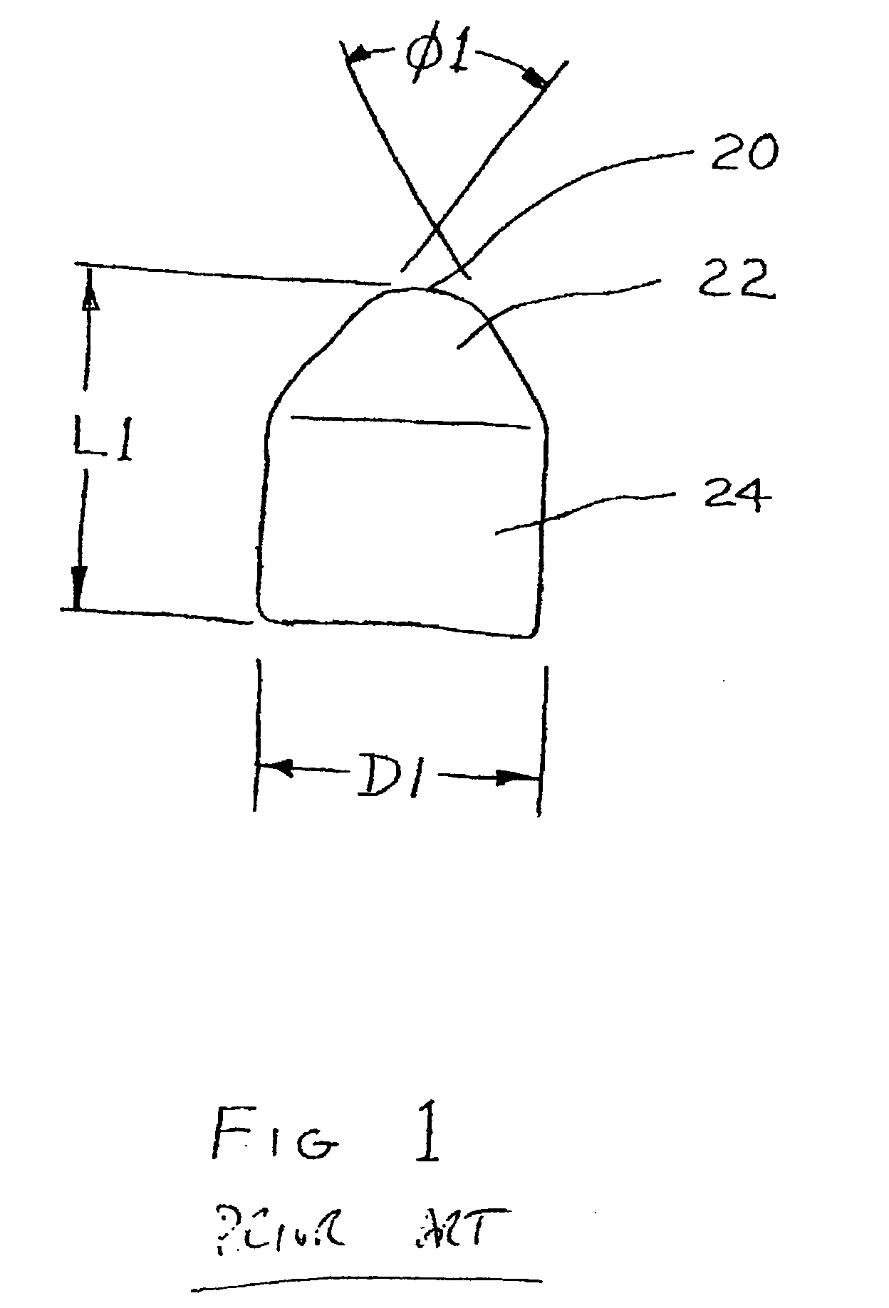
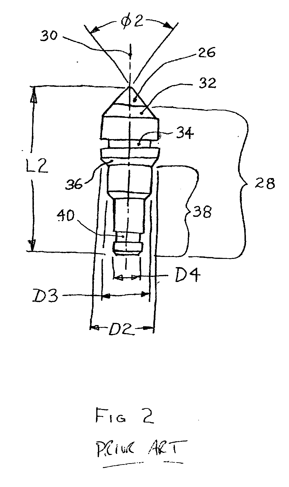
In harder formations, nonetheless, pointed and truncated contact structures can be damaged so rapidly that they are impractical to maintain.
This limitation has led to use of a radius or nose on the end of the contact element or structure, and the equipment employing such contact structures then applies higher forces.
Such designs have met with limited success, as the difference in hardness between the two grades of carbide used has not been great enough.
Such elements are limited to larger bit sizes, and their use is limited to shallow holes in relatively soft formations.
These bits use a relatively compact cutting element compared to the cutting elements commonly used in mining machinery because of the limited space available on a bit.
This design has not been well accepted in the drilling industry, likely because in this type of bit the bearings wear out before the tungsten carbide cutting elements do.
Polycrystalline diamond and cubic boron nitride are both substantially harder than impact grade of cemented tungsten carbide but are significantly less impact resistant.
The cost of polycrystalline diamond-coated contact structures is relatively high, and they are easily damaged and are generally not replaceable.
During use, polycrystalline diamond material has a tendency to delaminate from the tungsten carbide backing and to disintegrate.
Large numbers of diamonds are needed because the contact structures are small, they are irregular and the diamonds are brittle.
As a result the chips cut from the formation face are very small, and chip flushing is poor.
A second contact structure is adapted to cut deeper holes into soft and medium formations, and should cost more than the first design due to its increased complexity.
A third design is the most complex and is adapted to cut soft, medium, and medium hard formations, and will cost the most of the three.

Method used


Image

  • Rotary tools or bits
  • Rotary tools or bits
  • Rotary tools or bits

Examples


first embodiment

[0040] FIG. 3 is a partial cross section of a contact structure of the invention and a portion of a projection structure 48 of a cutting element. The contact structure and cutting element are fabricated from one material. This is the simplest embodiment of the present invention. The cross section is taken along the central axis 42 of the contact structure, which is generally radially symmetrical. A tip 44 at the distal end, a tapered face structure 46 extending from the distal end, and part of a projection or mounting structure 48 are shown.

[0041] The tip structure 44 in this embodiment is shown as flat because it is not possible to make a perfect point or edge in any material. Additionally, at some level of size for any given job, sharpness of the point creases to be a factor in how well the contact structure tip actually cuts or chips material. In any event, it is sometimes advantageous to limit the sharpness of the tip structure 44, as is shown in FIG. 3.

[0042] In the present inv...

second embodiment

[0045] FIG. 4 shows a contact element 50 and an end of a cutting element of a second embodiment, similar in shape to the contact structure shown in FIG. 3 but fabricated from two different materials. A first material 50, such as polycrystalline diamond or polycrystalline cubic boron nitride, provides or forms the contact element 54, at the tip, and a second material 52, such as cemented metal carbide, which forms the projection structure 56 and the tapered face feature 58. The second material supports the first material 50 through chemical, metallurgical, or mechanical bonding or through an engaging structure (not shown) as in FIG. 8, at 102, below. Welding, sintering, and brazing are suitable methods of attachment also.

[0046] FIG. 5 shows an embodiment of the present invention that includes a contact element column 60 of very hard material, such as polycrystalline diamond or polycrystalline cubic boron nitride, that is configured along the axis 62 of the structure. A second materia...

third embodiment

[0055] FIG. 11 shows a contact structure 124, 126 attached to a mounting structure in the invention. The mounting structure comprises a threaded element 128 and a circumferentially engageable element 130, which permits grasping and turning the element, as with a wrench. The threaded element 128 is tapered at an angle .PHI.8. The tapered form of the threaded element 128 allows cutting elements to be assembled more closely to each other in a bit assembly. The increased cutting element density helps stabilize the bit while cutting, by distributing the imposed loads. It also allows for the alignment of cutting elements in rows. An additional advantage of the tapered, threaded holding structure 128 is that it is self-locking. In the present invention the angle .PHI.8 is between 1 / 2 degree and 60 degrees. The circumferentially engageable feature 130 is a hexagon, but other forms can be used. Cutting elements that are threadably engageable as in FIG. 11 are fixed and are not rotatable. The...


PUM


Abstract

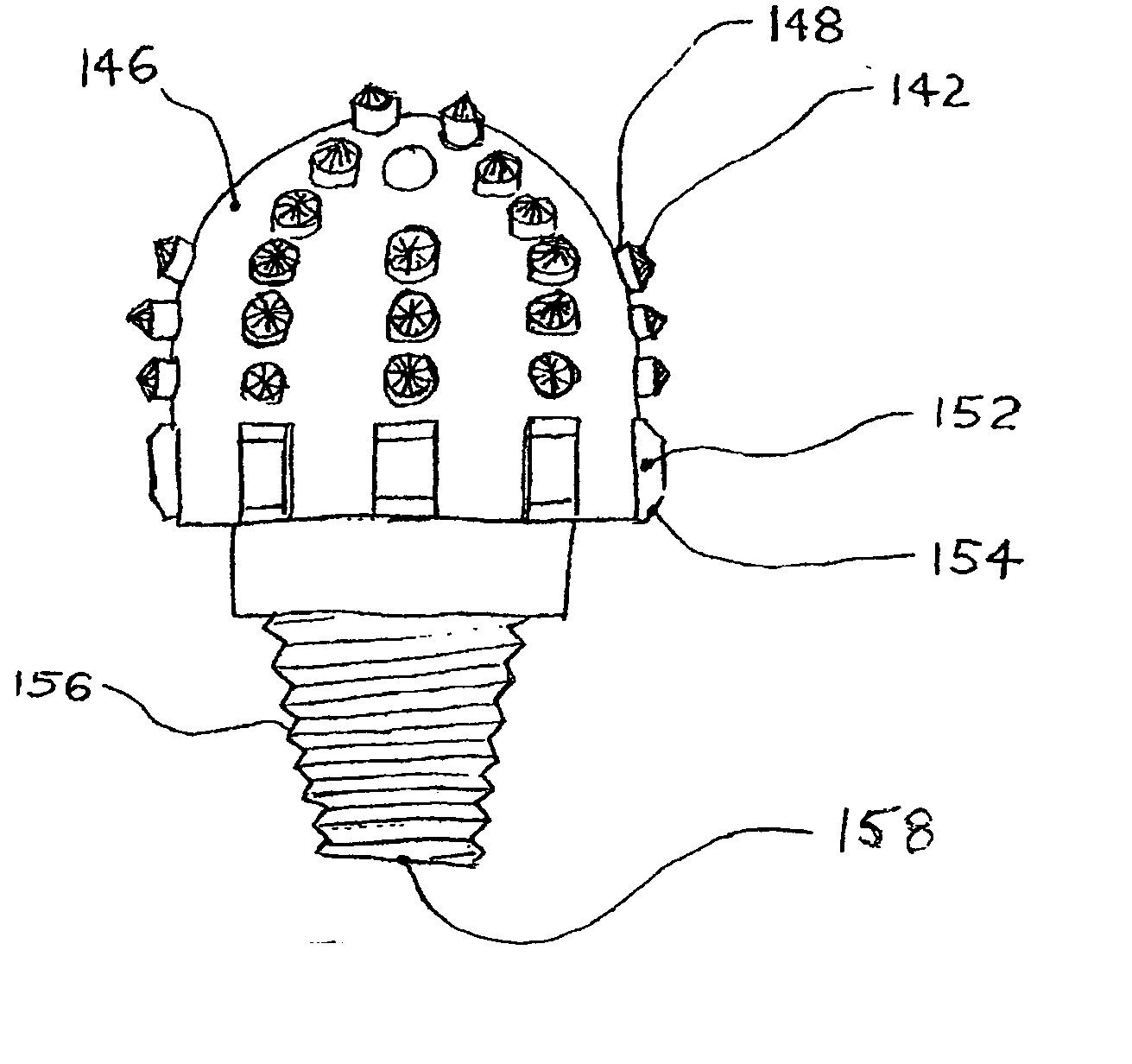
Rotary tools or bits carry cutter element including pointed contact structures and elements for chipping, cutting, and breaking non-ductile materials such as rock. The cutter elements directly contact and cut through rock and other materials and have tapered contact structure ends. Rotary tools or bits for carrying the cutter elements carry fixed cutter elements, or have sockets for removable threaded or rotatable cutter elements, arranged in straight or curved rows on the head opposite a drill-string-engaging base of the tool. The tools also have radially-extending buttresses which help to protect the cutter elements from damage as a drill string and bit are withdrawn from a bore.

Description

[0001] This invention relates to rotary tools used to drill, mill, or mine brittle formations, and it relates particularly to tools or bits using contact structures that are tapered and pointed and to cutting elements using such contact structures. Several new contact structures and cutting elements are disclosed for use in a family of earth-boring bits and of bodies for earth-boring bits.BACKGROUND OF THE ART[0002] The mining, construction, and drilling industries make extensive use of rotary tools. These tools apply intense loads to small areas to break brittle formation and structures into chips. Tapered cutting elements are commonly used for this purpose. Such elements are alternatively referred to as studs, buttons, cutters, cutting tools, and bits. A plurality of cutting elements may be attached to a holding tool. This tool may be a rotating drum, disc, or bit body. Such tools are used to mine minerals, cut trenches, mill pavement, drill holes, and the like.[0003] A cutting el...

Claims


Application Information

Patent Timeline
Patent Type & Authority Applications(United States)
IPC IPC(8): E21B10/42E21B10/43E21B10/58
CPCE21B10/43E21B10/58E21B10/62
Inventor DVORACHEK, HAROLD A.
Owner DVORACHEK HAROLD A
Why Eureka
Try Eureka