Electrically insulated switching element drive circuit

a technology of switching element and drive circuit, which is applied in the direction of electronic switching, power conversion system, pulse technique, etc., can solve the problems of circuit size and large overall scale of such a circui

Inactive Publication Date: 2004-11-25
DENSO CORP +1
View PDF9 Cites 94 Cited by
  • Summary
  • Abstract
  • Description
  • Claims
  • Application Information

AI Technical Summary

Benefits of technology

[0010] As a result, the control electrode drive circuit is supplied with operating power via the transformer while at the same time the control command signal is also transmitted through the transformer to the control electrode drive circuit, without it being necessary to provide means such as a photo-coupler system for transmitting the command contents to the control electrode drive circuit. Hence, the overall circuit configuration can be greatly simplified by comparison with the prior art, so that a more compact electrically insulated type of switching element drive circuit can be realized.
[0023] With such a configuration for the coreless transformer, it is preferably ensured that at least 80% of the printed conductor constituting the primary coil coincides in position with the printed conductor constituting the secondary coil, with respect to a direction at right angles to a main face of the circuit substrate. That is to say, the two coils are of substantially identical configuration and identical position on the circuit substrate, and differ in position only along the thickness direction of the circuit substrate. It can thereby be ensured that the electromagnetic coupling between respective turns of the primary coil and the secondary coil of the transformer can be maximized, thereby enabling the power transfer efficiency of the transformer to be enhanced.

Problems solved by technology

However it is necessary for such a circuit to use transistors which have high power-handling capability and the overall size of the circuit becomes excessive due to the size and weight of the transformer, so that the overall scale of such a circuit is large

Method used


Image

  • Electrically insulated switching element drive circuit
  • Electrically insulated switching element drive circuit
  • Electrically insulated switching element drive circuit

Examples


Embodiment Construction

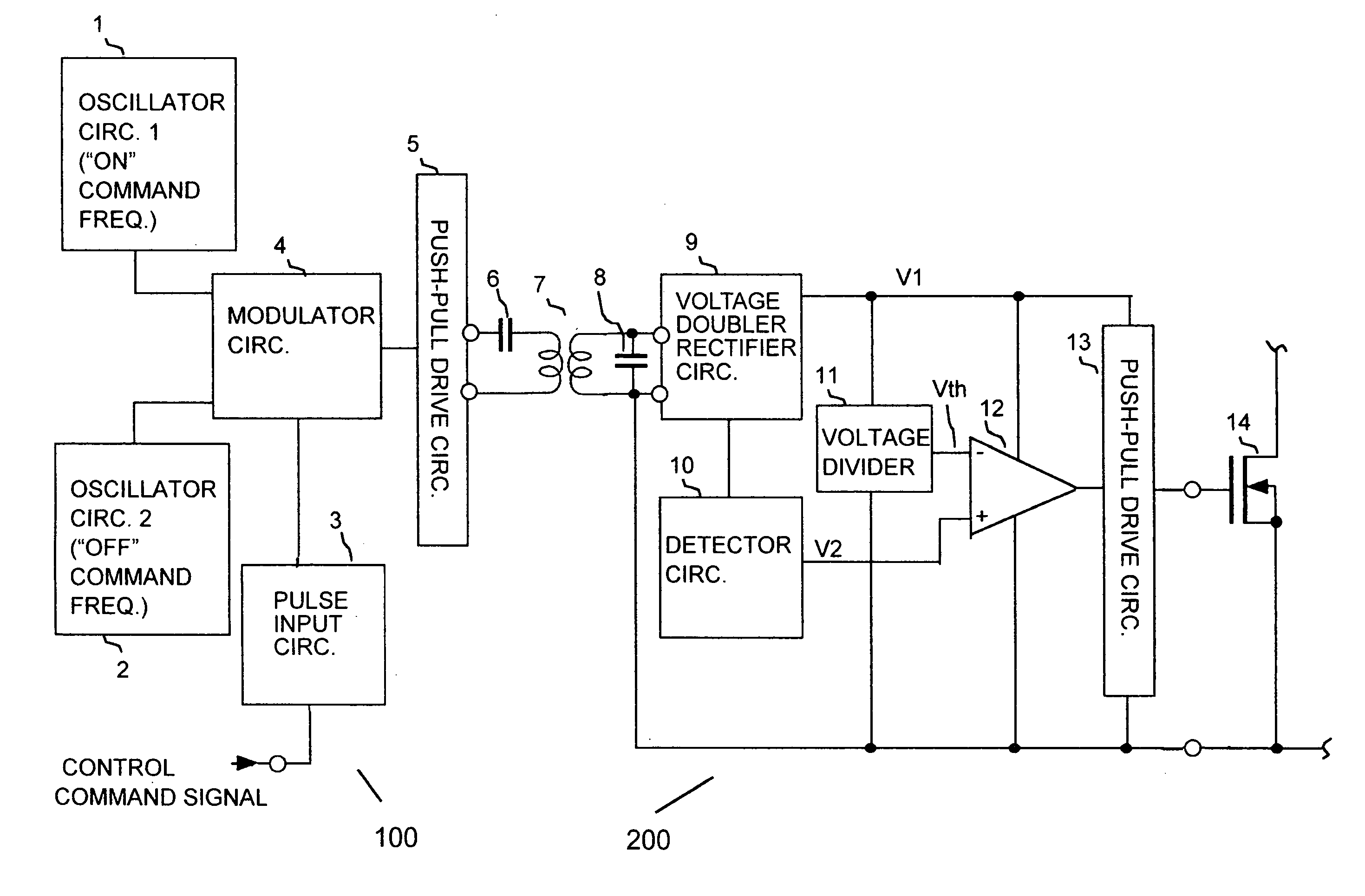
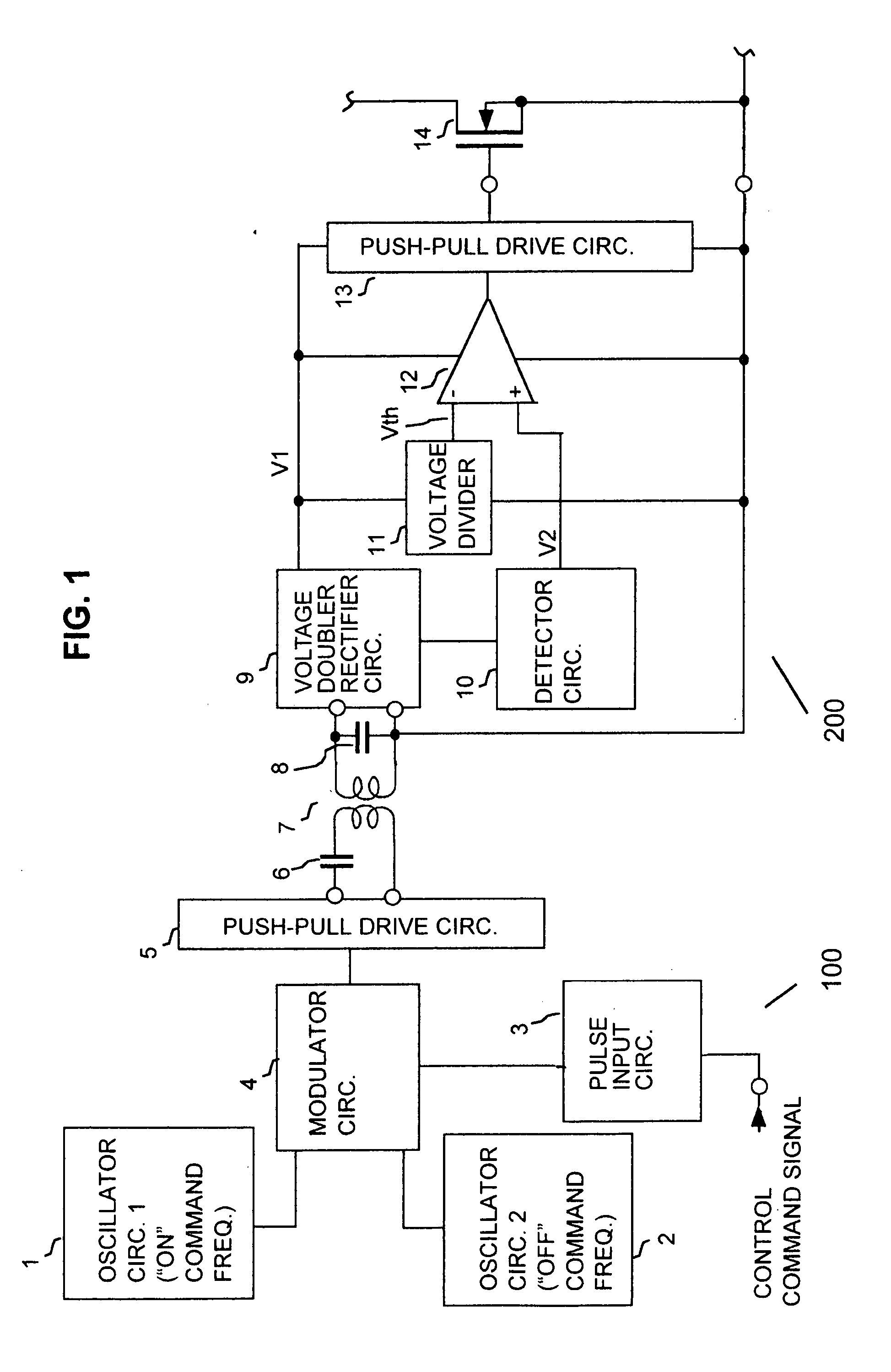
[0032] A preferred embodiment of an electrically insulated type of switching element drive circuit will be described referring to FIG. 1. In FIG. 1, numeral 1 denotes an "on" command-use oscillator circuit which is a sine-wave oscillator whose oscillation frequency corresponds to an on command status of a control command signal, indicating that a controlled switching element is to be set in the on state as described hereinafter. The oscillator signal (i.e., AC voltage, used as a carrier) from the "on" command-use oscillator circuit 1 is supplied to a modulator circuit 4, together with the oscillation signal from an "off" command-use oscillator circuit 2 which also is a sine-wave oscillator. The oscillation frequency of the "off" command-use oscillator circuit corresponds to an off command status of the control command signal, indicating that the controlled switching element is to be set in the off state. The control command signal is supplied from an external source to a pulse input...


PUM

PropertyMeasurementUnit
AC voltageaaaaaaaaaa
voltageaaaaaaaaaa
DC voltageaaaaaaaaaa

Abstract

An electrically insulated type of switching element drive circuit supplies an AC voltage via a transformer to a control electrode drive circuit that controls a switching element, with the frequency or amplitude of the AC voltage being modulated in accordance with required on / off operation of the switching element, and with the output AC voltage from the transformer being rectified to obtain a DC supply voltage that is continuously supplied to the control electrode drive circuit. The control electrode drive circuit detects a condition of the AC voltage and controls the switching element accordingly.

Description

[0001] 1. Field of Application[0002] The present invention relates to an electrically insulated type of switching element drive circuit, i.e., whereby a switching element is driven by a control circuit that is insulated from a source of a control command signal which selectively designates setting of the switching element to the on (i.e., conducting) and off (i.e., non-conducting) states, with the control circuit operating in accordance with that control command signal.[0003] 2. Description of Prior Art[0004] A DC-DC converter circuit or DC-AC inverter circuit generally is made up of an input circuit which produces a control signal and a drive circuit which supplies drive signals to the control electrodes of switching elements in accordance with the control signal, with the reference (ground) potential of the input circuit usually being different from that of the drive circuit. This is true for example of a drive circuit which drives a high-side switching element of a DC-AC inverter...

Claims


Application Information

Patent Timeline
Patent Type & Authority Applications(United States)
IPC IPC(8): H01F30/00H02M1/08H03K17/06H03K17/61H03K17/691
CPCH03K17/063H03K17/691
Inventor KAWASAKI, KOJIYAMASHITA, TSUYOSHI
Owner DENSO CORP
Why Eureka
Try Eureka