Automatic telescope

a telescope and automatic technology, applied in the field of telescopes, can solve the problems of difficult use, small interfaces of telescopes, and inability to familiarize,

Inactive Publication Date: 2004-11-25
BUSHNELL
View PDF9 Cites 38 Cited by
  • Summary
  • Abstract
  • Description
  • Claims
  • Application Information

AI Technical Summary

Problems solved by technology

Unfortunately, many users are not familiar with or do not want to be bothered with providing such information.
Additionally, such telescopes typically only have small hard-to-use interfaces, such as handheld remote controls.
While these remote controls are adequate for some purposes, they can be difficult to use, further increasing the inconvenience of providing orientation information.

Method used


Image

  • Automatic telescope
  • Automatic telescope
  • Automatic telescope

Examples


Embodiment Construction

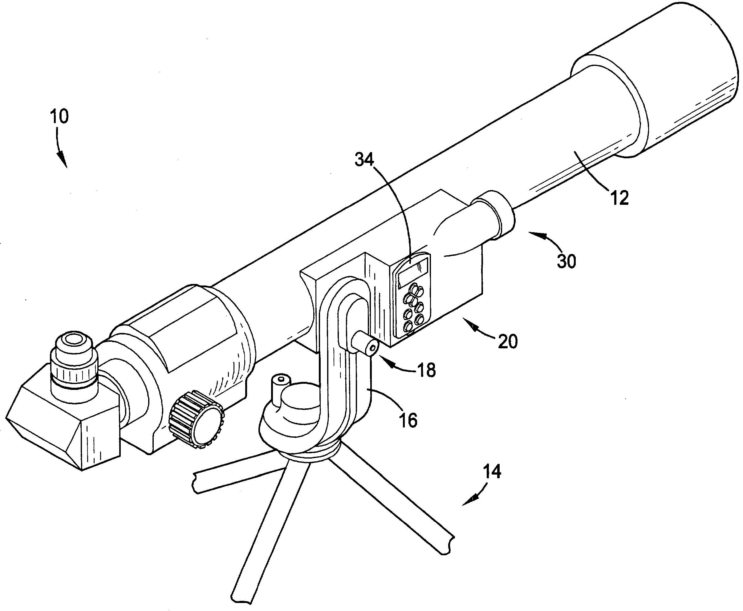
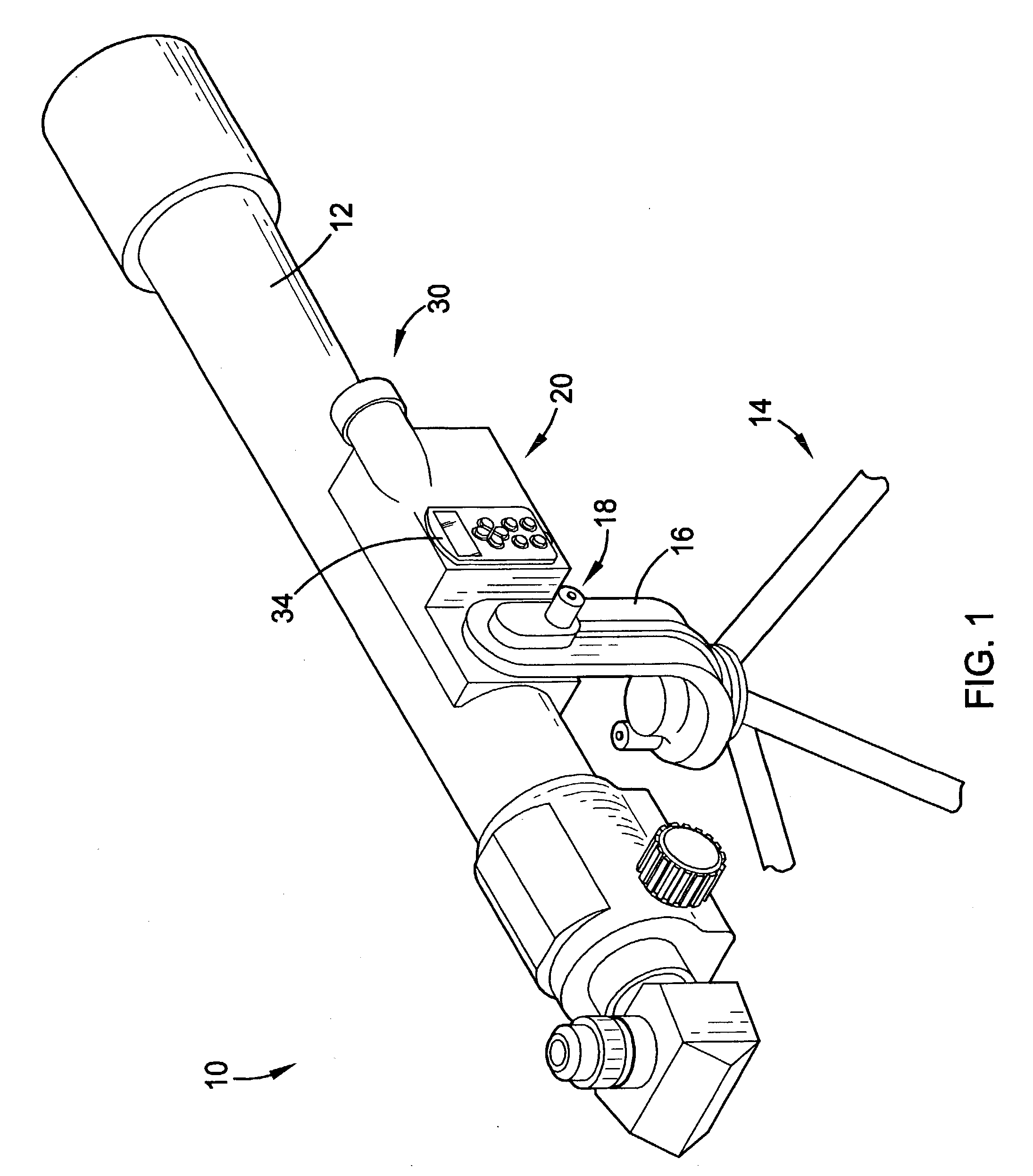
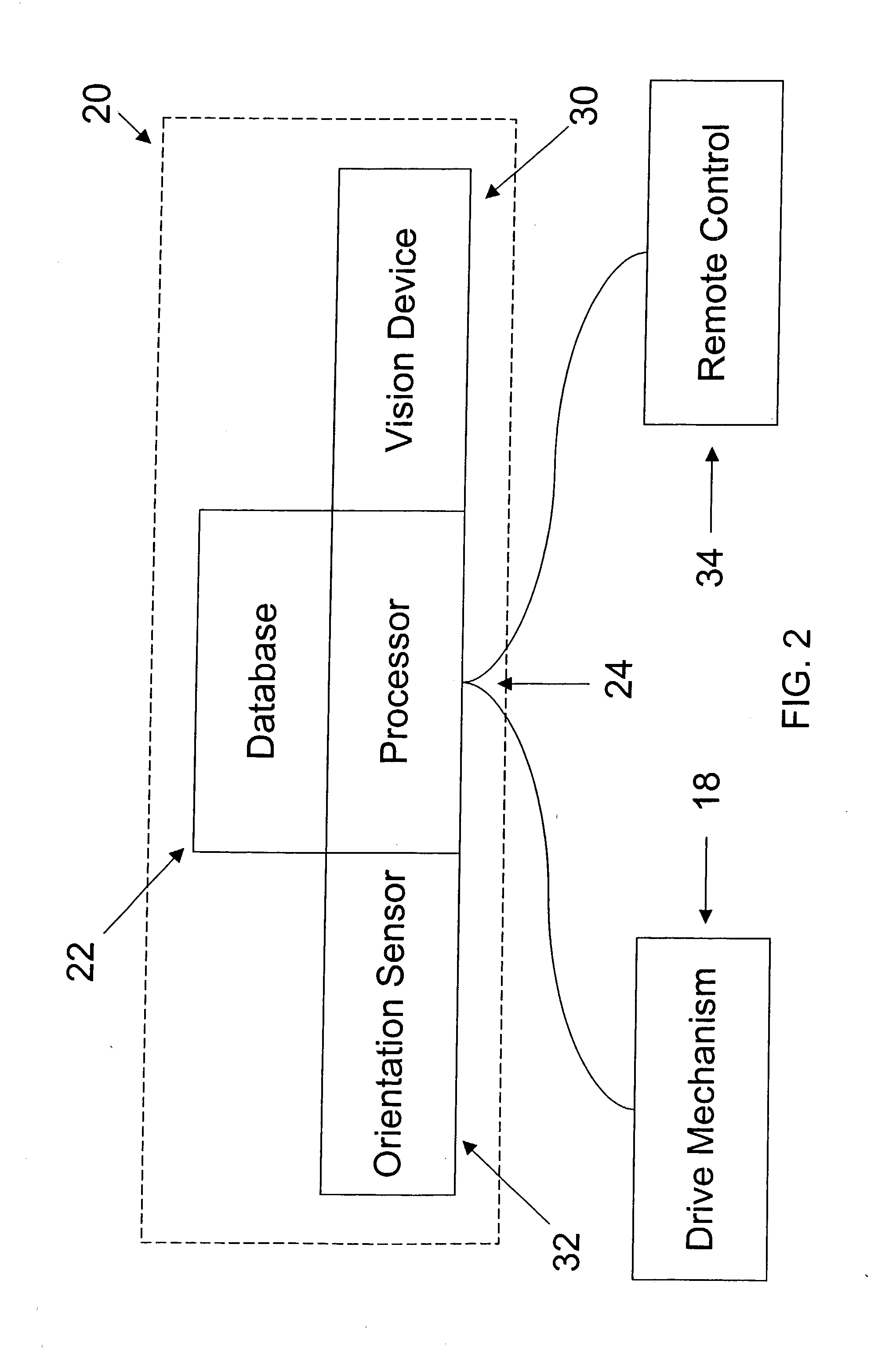
[0022] Referring to FIG. 1, the preferred automatic telescope 10 constructed in accordance with a preferred embodiment of the present invention is illustrated as a stand-alone system capable of determining an orientation of the telescope 10 without requiring input from a user. Additionally, the telescope 10 may automatically align itself with virtually any star or other celestial object specified by the user. As such, the telescope 10 of the present invention preferably incorporates capabilities shown in "AUTO-ALIGNMENT TRACKING TELESCOPE MOUNT", U.S. Pat. No. 6,369,942, hereby incorporated into the present application by reference. The telescope 10 broadly comprises an optical telescopic tube 12 for magnifying distant objects, a base 14 for supporting the tube 12, a cradle 16 for securing the tube 12 to the base 14, a drive mechanism 18 for moving the tube 12 with respect to the base 14, and a control unit 20 to control the drive mechanism 18.

[0023] The tube 12 is preferably conven...


PUM


Abstract

An automatic telescope (10) capable of determining an orientation without requiring input from a user or any external source. The telescope (10) preferably includes a database (22) to store astronomical information, a processor (24) to control a drive mechanism (18), a vision device (30) to sense bright stars, and a motion sensor (32) to generate a motion signal. When the vision device (30) is slewed from alignment with a first bright star to a second bright star, the motion signal is preferably representative of a measured angle between the first and second bright stars. This process is preferably repeated for several bright stars to generate several measured angles. The processor (24) can then use the measured angles to identify the bright stars and determine the orientation of the telescope (10).

Description

[0001] 1. Field of the Invention[0002] The present invention relates to telescopes. More particularly, the present invention relates to an automatic telescope that can align itself in order to view a specified star.[0003] 2. Description of Prior Art[0004] Many telescopes are capable of finding and tracking stars and other celestial bodies. However, these telescopes must be initially oriented and re-oriented each time they are moved. Therefore, users are typically required to provide such telescopes with orientation information, such as an altitude angle and an azimuth angle. Unfortunately, many users are not familiar with or do not want to be bothered with providing such information.[0005] Additionally, such telescopes typically only have small hard-to-use interfaces, such as handheld remote controls. While these remote controls are adequate for some purposes, they can be difficult to use, further increasing the inconvenience of providing orientation information.[0006] Accordingly, ...

Claims


Application Information

Patent Timeline
Patent Type & Authority Applications(United States)
IPC IPC(8): G02B23/00G02B23/16
CPCG02B23/00G02B23/16Y10S359/90
Inventor MCWILLIAMS, RICK
Owner BUSHNELL
Why Eureka
Try Eureka