
Headlamp bulb

a headlamp and bulb technology, applied in the direction of electric discharge lamps, coupling device connections, lighting and heating apparatus, etc., can solve the problems of dust entering the lamp base, and achieve the effect of preventing lamp maladjustment and facilitating the welding of the lamp holder to the reference ring

Inactive Publication Date: 2004-12-02
PATENT TREUHAND GESELLSCHAFT FUR ELECTRIC GLUEHLAMPEN MBH
View PDF8 Cites 4 Cited by
  • Summary
  • Abstract
  • Description
  • Claims
  • Application Information

AI Technical Summary

Benefits of technology

[0007] The annular metallic holder is advantageously provided with a rim which rests on the annular surface of the reference ring and is connected to it. The welding of the holder to the reference ring is thereby facilitated. The reference noses are advantageously designed to be cambered in the region of their edges running radially with reference to the reference ring. This prevents any sharp edges of the reference noses from causing wear on the reflector wall which could lead to dirt deposits in the headlight. Moreover, the reference ring and the base flange advantageously form an undercut, in order to prevent maladjustment of the lamp in the headlight by a possible burr on the reflector neck. For this purpose, an annular groove is advantageously arranged in the region of the contact surface of the reference ring and the base flange.

Problems solved by technology

Owing to the adjustment of the incandescent filament with reference to the reference noses, when the base is being mounted undesired slots or openings can result in the lamp base, and so dust can penetrate into the lamp base.

Method used


Image

  • Headlamp bulb
  • Headlamp bulb
  • Headlamp bulb

Examples


Embodiment Construction

[0008] The invention is explained in more detail below with the aid of a preferred exemplary embodiment. In the drawing:

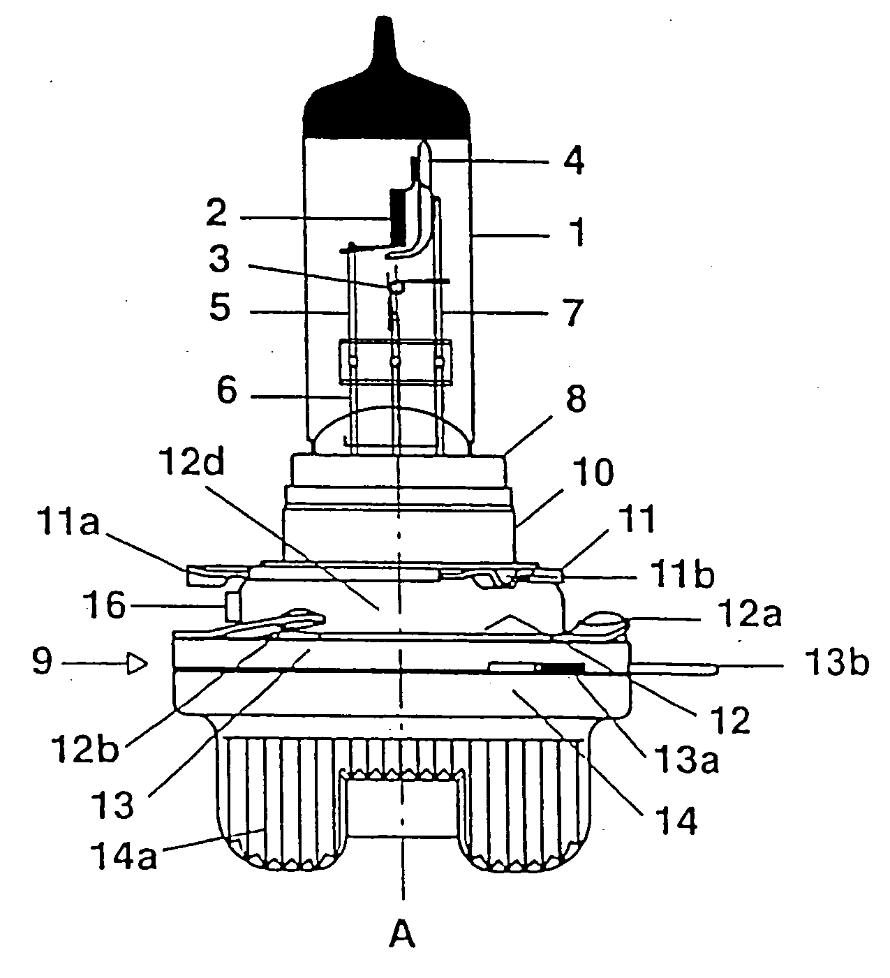
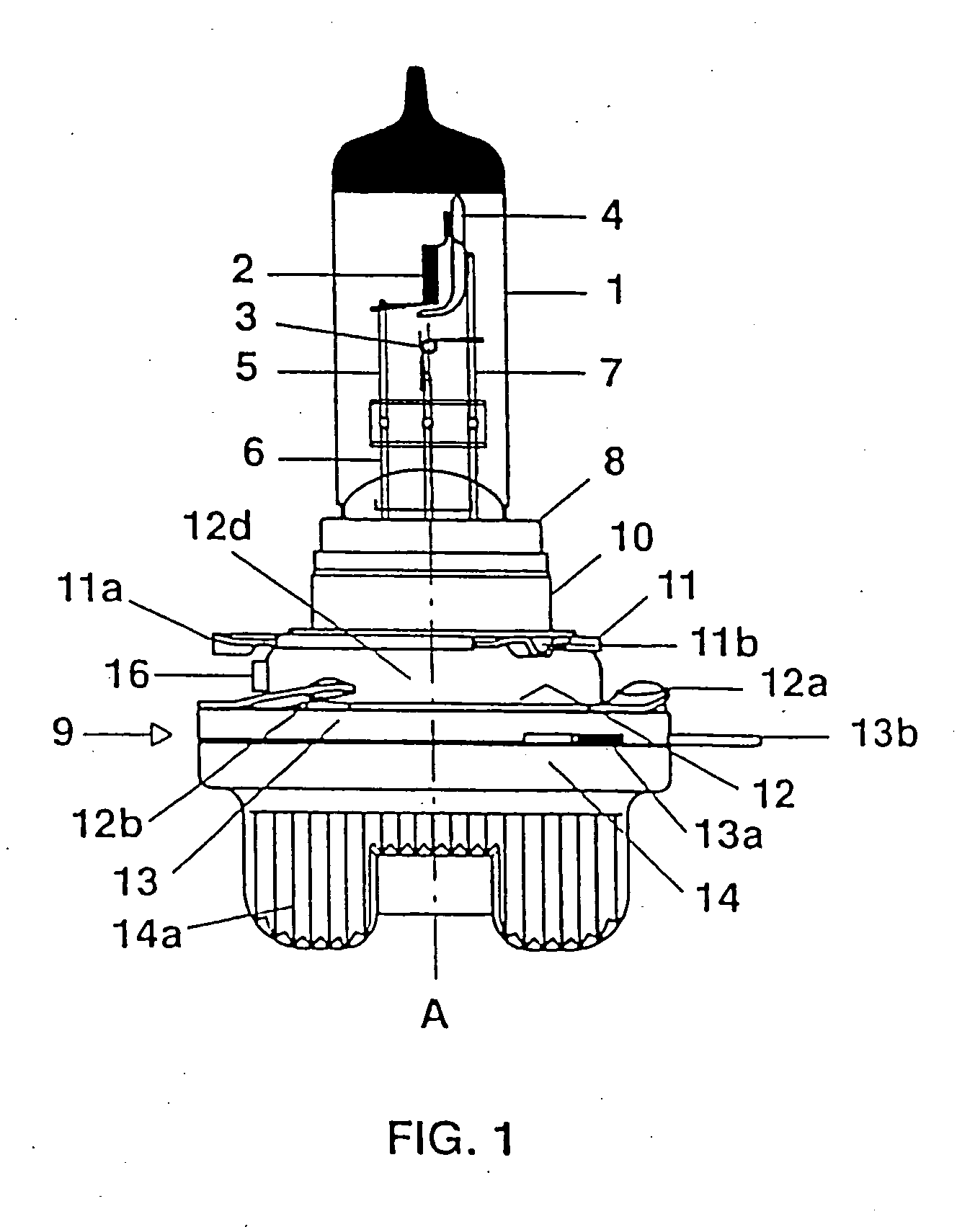
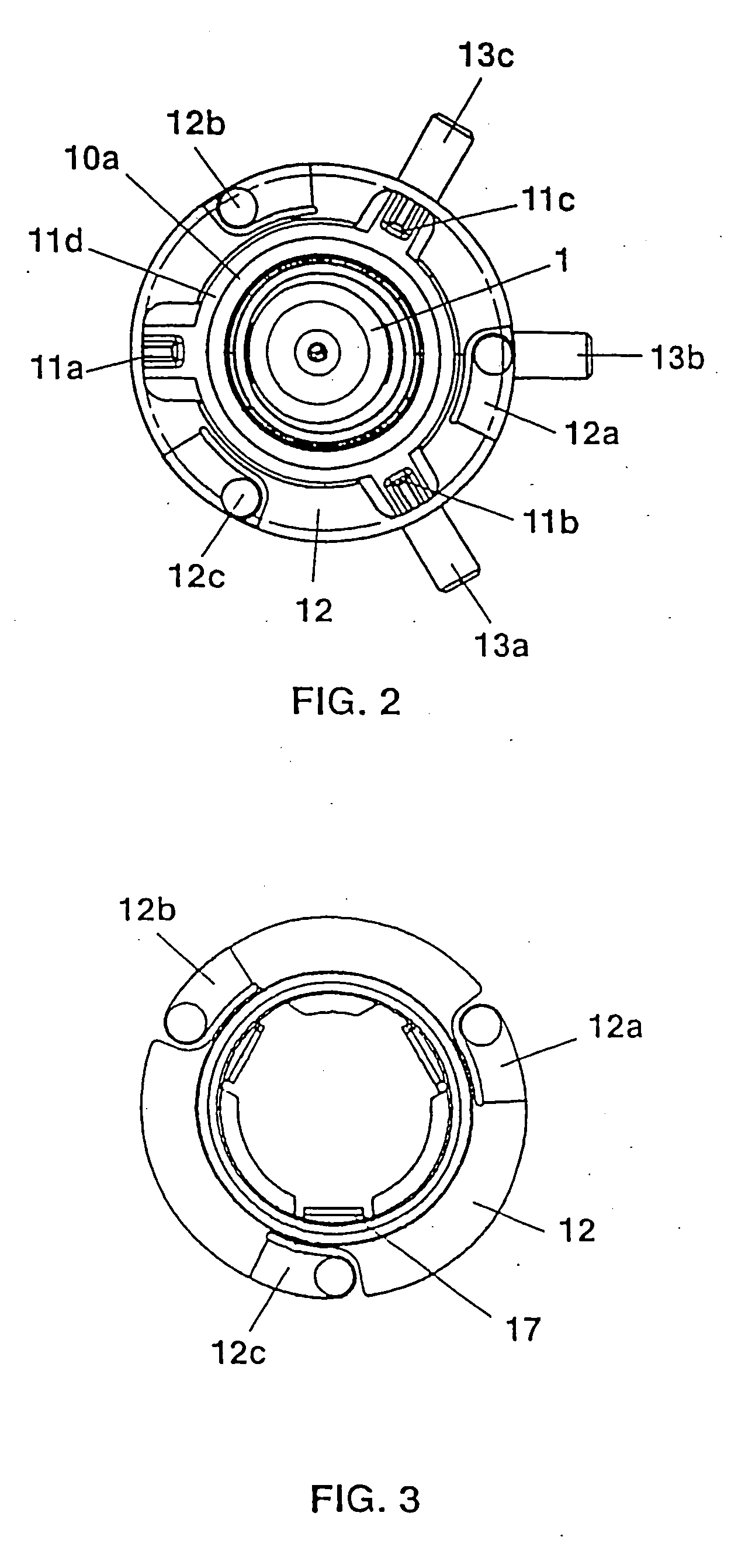
[0009] FIG. 1 shows a side view of the preferred exemplary embodiment of the headlight lamp according to the invention,

[0010] FIG. 2 shows a plan view of the headlight lamp illustrated in FIG. 1, and

[0011] FIG. 3 shows a plan view of the base flange of the lamp illustrated in FIG. 1,

[0012] FIG. 4 shows a plan view of the reference ring of the lamp illustrated in FIG. 1, and

[0013] FIG. 5 shows a side view of a reference nose of the reference ring illustrated in FIG. 4.

[0014] The preferred exemplary embodiment, illustrated in FIG. 1, of the invention is a two-filament halogen incandescent lamp which is provided for insertion into a motor vehicle headlight. This lamp has a vitreous, essentially cylindrical lamp vessel 1, inside which there are enclosed two incandescent filaments 2, 3 of which one is arranged axially and the other in a transverse fashion to the longitu...


PUM


Abstract

The invention relates to a headlight lamp having at least one lamp vessel (1) in which at least one luminous means (2, 3) is enclosed, and having a lamp base (9) which is provided with the electric terminals of the headlight lamp. The lamp base (9) has an annular metallic holder (8, 10) in which the at least one lamp vessel (1) is fixed, and at least three reference noses (11a, 11b, 11c) arranged in a common plane, as well as an annular base flange (12), the base flange plane being arranged parallel to the plane of the reference noses (11a-11c), and the base flange (12) being provided with at least three lugs (12a, 12b, 12c), which are arranged along its circumference, are of resilient design and serve together with the reference noses (11a, 11b, 11c) for fastening the lamp in a headlight. According to the invention, the reference noses (11a, 11b, 11c) are integrally formed on a reference ring (11) which is connected to the annular metallic holder (8, 10) and to the base flange (12), and which has a flat annular surface (11d) arranged parallel to the base flange plane, the outside diameter of the annular surface (11d) being greater than or equal to the inside diameter of the base flange (12) and greater than or equal to the outside diameter of the annular metallic holder (8, 10), and the inside diameter of the annular surface (11d) being smaller than the inside diameter of the base flange (12) and smaller than the outside diameter of the annular metallic holder (8, 10).

Description

[0001] The invention relates to a headlight lamp in accordance with the preamble of patent claim 1.I. PRIOR ART[0002] Such a headlight lamp is disclosed, for example, in German Laid-open Patent Application DE 199 51 203 A1. This patent application describes a headlight lamp having a lamp vessel, an incandescent filament enclosed therein, and a lamp base which is provided with the electric terminals of the headlight lamp. The lamp base has an annular metallic holder for anchoring the lamp vessel. Moreover, the lamp base has three reference noses arranged in a common plane, and an annular base flange, the base flange plane being arranged parallel to the plane of the reference noses. The base flange is provided with three lugs of resilient design which are arranged along its circumference and serve together with the reference noses for fastening the lamp in a headlight. Owing to the adjustment of the incandescent filament with reference to the reference noses, when the base is being mo...

Claims


Application Information

Patent Timeline
IPC IPC(8): F21V7/04F21S8/10F21V19/00F21W101/10F21Y101/00H01J5/56H01KH01K1/46H01K7/02
CPCH01K1/46H01J5/56
Inventor BEHR, GERHARDHELBG, PETER
Owner PATENT TREUHAND GESELLSCHAFT FUR ELECTRIC GLUEHLAMPEN MBH
Learn More