Ultrasonic transmitter, ultrasonic transceiver and sounding apparatus

a transceiver and ultrasonic technology, applied in the field of ultrasonic transceivers and sounding devices, can solve the problems of deterioration of efficiency, deterioration of efficiency, and the inability of vibrating elements xd to continuously transmit ultrasonic signals, and achieve the effect of reliably controlling the amplitude of emitted ultrasonic signals, high efficiency, and simple structur

Active Publication Date: 2004-12-02
FURUNO ELECTRIC CO LTD
View PDF9 Cites 16 Cited by
  • Summary
  • Abstract
  • Description
  • Claims
  • Application Information

AI Technical Summary

Benefits of technology

[0026] Like the ultrasonic transmitter employing the half-bridge circuit, the ultrasonic transmitter employing the full-bridge circuit makes it possible to continuously transmit ultrasonic signals by repetitively causing resonance of each vibrating element and maintaining consequent vibration thereof in the aforementioned manner.
[0030] The aforementioned ultrasonic transmitter of the invention includes a driver circuit for generating driving pulse signals used for causing the vibrating elements to vibrate, the driver circuit being formed essentially of a half-bridge circuit including two switching devices or of a full-bridge circuit including four switching devices. The present invention makes it possible to configure a highly efficient transmitting beamformer featuring a simple structure that can reliably control the amplitude of emitted ultrasonic signals by controlling the switching devices of the bridge circuit.
[0031] In addition, the invention provides a sounding apparatus which can successively scan desired sounding directions, obtain received echo data derived from a particular search area based on echo signals received from the individual sounding directions, and display the received echo data to enable an operator to accurately recognize a detected echo image for multiple sounding directions substantially at the same point in time. Such a high-performance sounding apparatus can be configured by employing the aforementioned ultrasonic transceiver including the receiving beamformer and the device for controlling the transmitting beam and the receiving beam.

Problems solved by technology

Consequently, the vibration of the vibrating element XD is extremely attenuated and, when the vibrating element XD continuously radiates ultrasonic waves at a decreased amplitude, power loss increases resulting in deterioration of efficiency.
If the vibrating element XD stops to vibrate before a succeeding driving pulse is fed into the vibrating element XD due to an extremely large amount of attenuation of vibration, the vibrating element XD would no longer be able to continuously transmit the ultrasonic signal.
Consequently, as is the case with the aforementioned full-bridge circuit, the vibration of the vibrating element XD is extremely attenuated and, when the vibrating element XD continuously radiates ultrasonic waves at a decreased amplitude, power loss increases resulting in deterioration of efficiency.
The conventional half-bridge circuit thus configured, however, still has a problem in that the provision of the switching device FET.sub.3 connected parallel to the vibrating element XD results in a complex circuit configuration.

Method used


Image

  • Ultrasonic transmitter, ultrasonic transceiver and sounding apparatus
  • Ultrasonic transmitter, ultrasonic transceiver and sounding apparatus
  • Ultrasonic transmitter, ultrasonic transceiver and sounding apparatus

Examples


first embodiment

[0043] A scanning sonar according to a first embodiment of the invention is now described referring to the appended drawings.

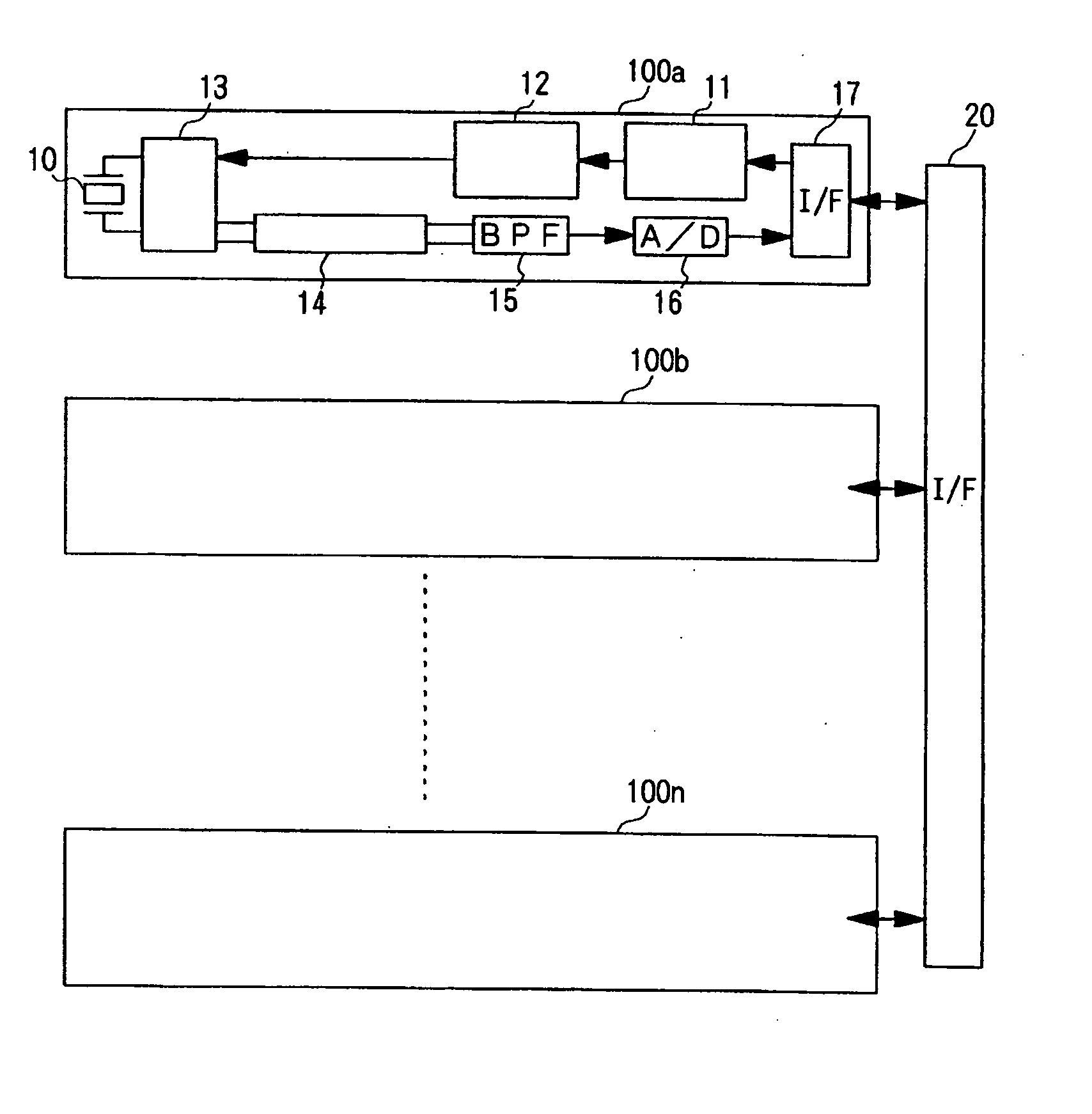
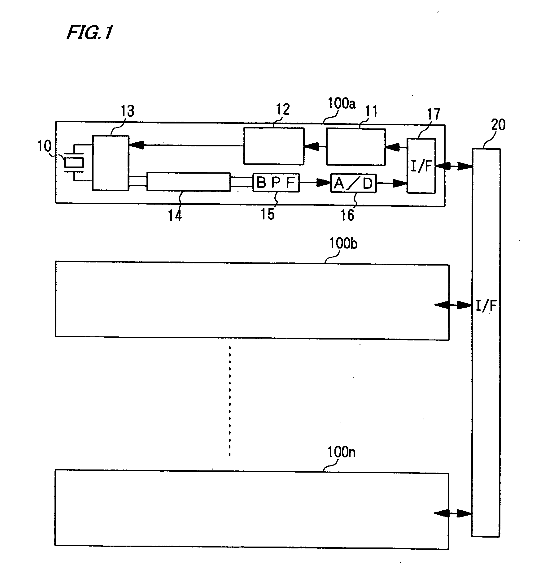
[0044] FIG. 1 is a block diagram generally showing the configuration of transmit-receive channels 100 of the scanning sonar according to the first embodiment. Referring to FIG. 1, each of the transmit-receive channels 100 includes a driver interface 11 which generates a drive signal for controlling a driver circuit 12 based on a clock signal and a digital-formatted control signal for controlling switching operation supplied from a later-described programmable transmitting beamformer 26. In this invention, the driver interface 11 and the programmable transmitting beamformer 26 together constitute a drive signal generator. The programmable transmitting beamformer 26 includes a waveform memory 24 which stores multiple patterns of control signals corresponding to ultrasonic signals having different amplitudes. When the amplitude of an ultrasonic signal to be radia...

second embodiment

[0069] An ultrasonic transceiver according to a second embodiment of the invention is now described referring to the appended drawings.

[0070] The ultrasonic transceiver of this embodiment is characterized by employing the same driver circuit 12 as shown in FIG. 1 combined with a full-bridge circuit shown in FIG. 6, which is conventional, to input drive signals 111, 112, 121 and 122 shown in FIGS. 5A-5D. The ultrasonic transceiver of this embodiment has otherwise the same construction as that of the first embodiment, so that part of the ultrasonic transceiver of the second embodiment identical to that of the first embodiment is not rediscussed in the following.

[0071] Switching devices FET.sub.11, FET.sub.12, FET.sub.21, FET.sub.22 of the full-bridge circuit shown in FIG. 6 correspond, respectively, to first to fourth switching devices recited in claim 2 of the invention.

[0072] The driver circuit 12 of each transmit-receive channel 100 incorporates the full-bridge circuit including fo...


PUM


Abstract

A driver circuit for generating a driving pulse signal to activate a vibrating element includes a half-bridge circuit formed essentially of first and second switching devices to which drive signals are supplied through a driver interface. A driving voltage is supplied to a source of the first switching device, a drain of the second switching device is grounded, and an output terminal of the half-bridge circuit is connected to the vibrating element. The half-bridge circuit is controlled such that the two switching devices alternately turn ON. When the first switching device is ON, the driving voltage is supplied as the driving pulse signal to the vibrating element, and when the second switching device is ON, the vibrating element and the second switching device together form a low-impedance closed loop. As the switching devices are caused to alternately turn ON at specific intervals, the vibrating element vibrates at a natural resonant frequency, transmitting thereby an ultrasonic signal.

Description

[0001] 1. Field of the Invention[0002] The present invention relates to an ultrasonic transmitter for radiating ultrasonic waves, an ultrasonic transceiver for radiating ultrasonic waves and receiving echoes of the radiated ultrasonic waves, and a sounding apparatus including an ultrasonic transceiver for detecting objects using ultrasonic waves.[0003] 2. Description of the Related Art[0004] Today, sonar apparatuses, such as scanning sonars, are widely used for detecting underwater objects (targets). A scanning sonar for detecting underwater objects in all surrounding directions has a generally cylindrical transducer. The scanning sonar forms an ultrasonic transmitting beam oriented in all directions around the transducer by activating vibrating elements arranged on a cylindrical surface of the transducer. Also, the scanning sonar forms a receiving beam oriented in a particular horizontal direction using a specific number of vertically arranged sets, or columns, of vibrating element...

Claims


Application Information

Patent Timeline
Patent Type & Authority Applications(United States)
IPC IPC(8): G01S15/06B06B1/02G01S7/521G01S7/523G01S7/524G10K11/34
CPCB06B1/0238B06B1/0269B06B2201/74G01S7/521G01S7/524G10K11/346
Inventor HAYASHI, TATSUO
Owner FURUNO ELECTRIC CO LTD
Why Eureka
Try Eureka