
Single use safety syringe

a safety syringe and single-use technology, applied in the direction of intravenous devices, infusion needles, infusion devices, etc., can solve the problems of high manufacturing cost, high manufacturing cost, and re-use of disposable medical equipment, so as to facilitate the shielding of the sharp point

Inactive Publication Date: 2004-12-02
AFRICAN VENTURES & TECH
View PDF16 Cites 16 Cited by
  • Summary
  • Abstract
  • Description
  • Claims
  • Application Information

AI Technical Summary

Benefits of technology

[0003] The present invention provides a safety device for a syringe needle which includes, a guide mounted on the barrel of a syringe or being an integral moulded part of the barrel, a slidable member with a first portion configured to be slid along the guide and a second portion having a formation for a needle, that facilitates the shielding of the sharp point within that formation.
[0015] A Z-shaped guide can include a first, second and third leg, with a first apex point between the first and second leg and a second apex point between the second and third leg. In this instance the syringe would typically be ready for use with the plunger fully inserted into the barrel of the syringe. The first and second apex can have a means for encouraging a one-directional pathway of the followers. This means can be in the form of compressible moulded protrusions with a stepped incline preventing re-entry into a preceding leg.
[0017] A V-shaped guide and can include a first and second leg, with an apex point between the first and second leg. A means for encouraging a one-directional pathway of the followers can be located within the apex and can be in the form of compressible moulded protrusions with a stepped incline preventing re-entry into a preceding leg.
[0020] This second leg of the V-shape is in communication with the exterior of the plunger and in so doing allows the follower to slide out of the V-shape guide and thereby disassociates the first part of the plunger from the second part of the plunger, causing the second part to remain at the needle end of the syringe.

Problems solved by technology

However these generally exhibit disadvantages such as requiring both hands of the healthcare worker to operate and / or having a high manufacturing cost.
The cost of medical care in impoverished third world countries has resulted in the re-use of disposable medical equipment, often without adequate sterilization.
In light of the high incidence of HIV and related illnesses in these countries, this situation is unacceptable.
Patient education is often not optimal; and the unsophisticated patient is more likely to accept re-used equipment.
Available mechanisms to render syringes non-reusable have been found to be expensive and some are even made re-usable by the determined user.

Method used


Image

  • Single use safety syringe
  • Single use safety syringe
  • Single use safety syringe

Examples


Embodiment Construction

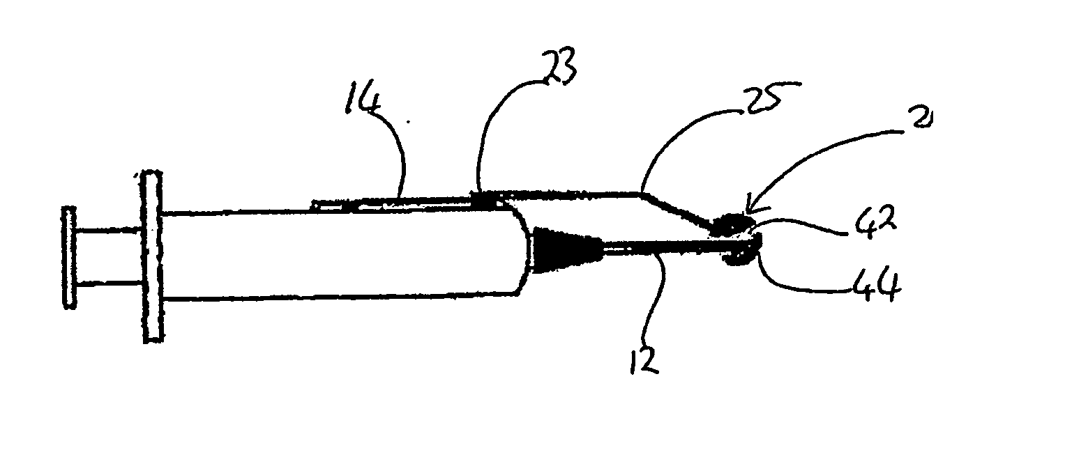
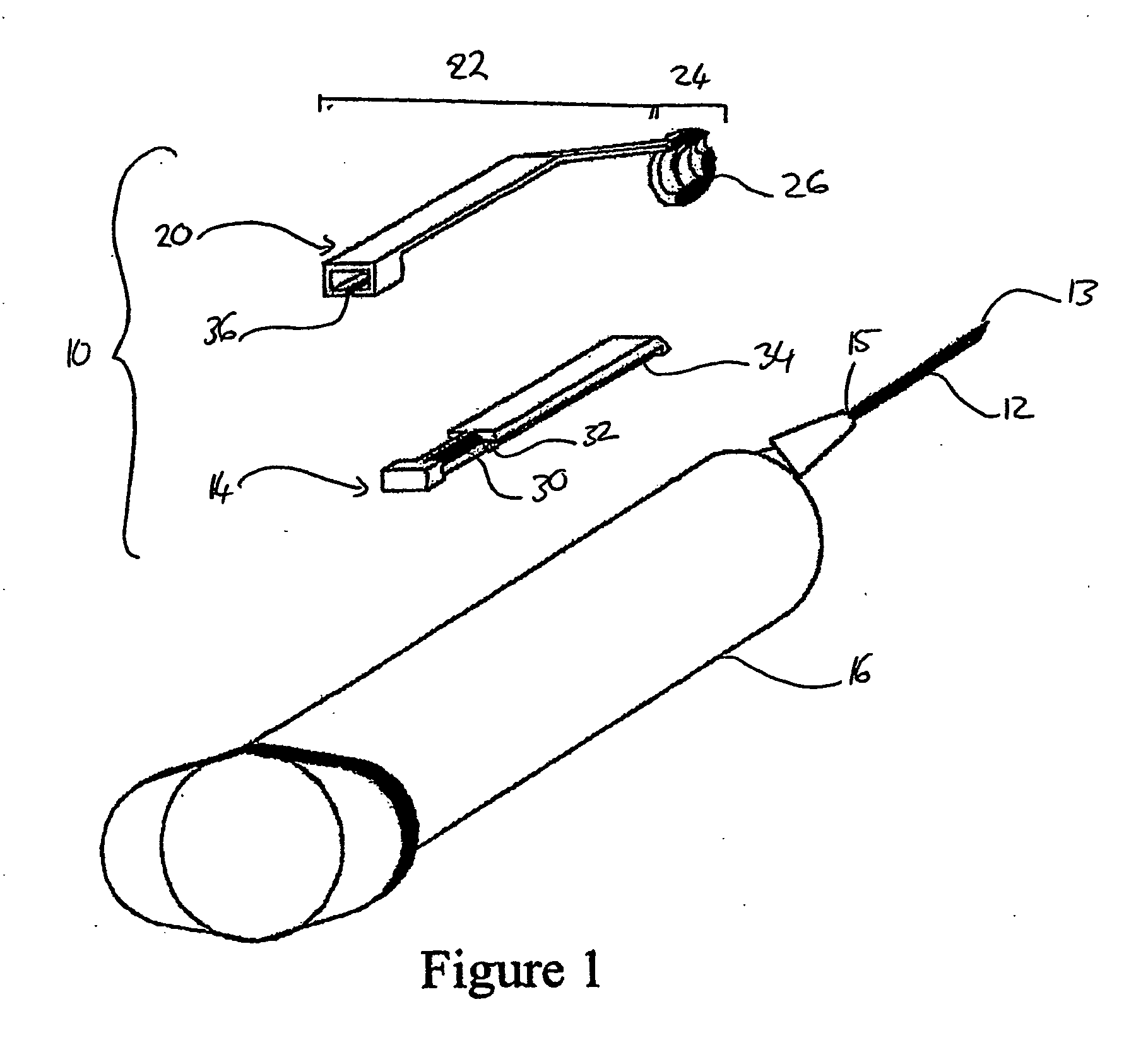
[0033] As shown in the FIGS. 1 to 7, the safety device 10 for a syringe needle 12 includes, a guide 14 mounted on the barrel 16 of a syringe 18 or being an integral moulded part of the barrel 16 and a slidable member 20 with a first portion 22 configured to be slid along the guide 14 and a second portion 24 having a formation 26 for a needle 12, that facilitates the shielding of the sharp point 13 within that formation 26.

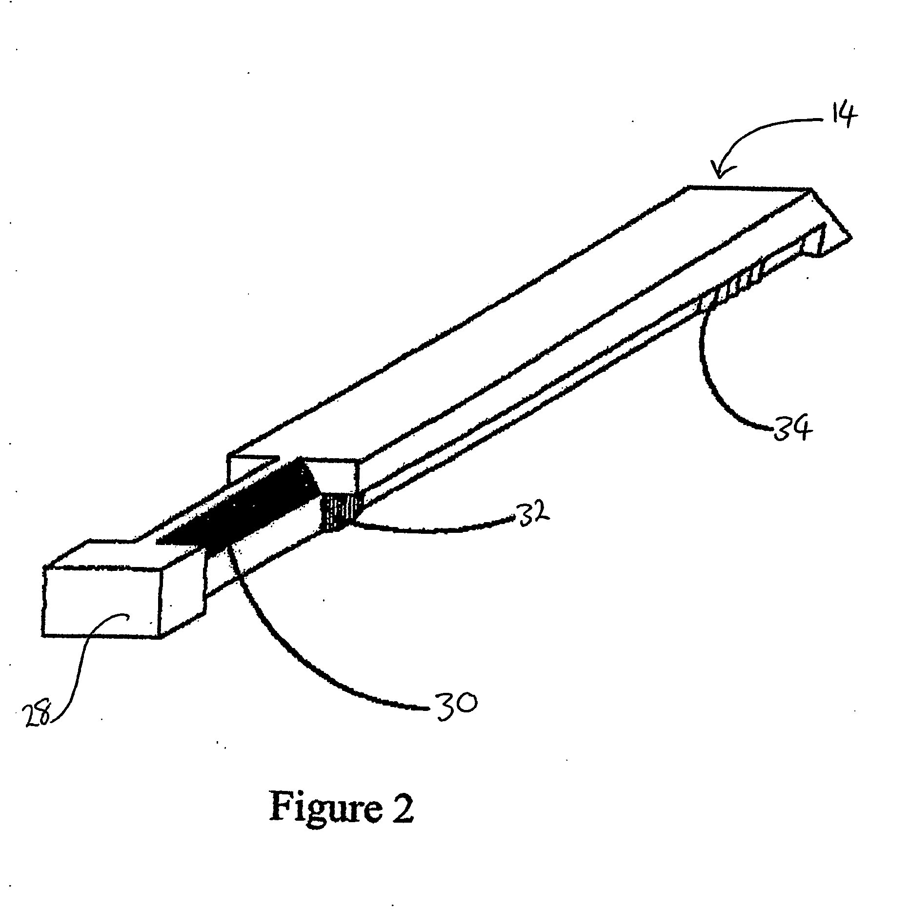
[0034] The guide 14 has proximal and distal ends. The proximal end is defined by a terminal block 28 that prevents the first portion 22 of the slidable member from disengaging from the guide 14 at the proximal end, a bevelled segment 30 that allows for connection with the first portion 22 of the slidable member and a chamfered segment 32 to facilitate the temporary positioning of the first portion 22 before the slidable member 20 is advanced to engage with the needlepoint 13. The distal end of the guide 14 is defined by a segment of aligned toothed serrations 34 th...


PUM


Abstract

A safety device for a syringe needle, which includes a guide and a slidable member having a first portion that is configured to be slid along the guide and a second portion having a formation for a needle, that facilitates the shielding of the sharp point within said formation. A non-reusable syringe, which includes a plunger having a first part with one or more followers and a second part housing a guide.

Description

[0001] The present invention lies in the field of safety syringes, particularly those that prevent needle stick injuries and that are rendered permanently non-reusable.[0002] With the ever-increasing risk of acquiring the Human Immunodeficiency Virus and other blood-born infections, a need exists for a reliable, easy-to-use and cost effective safety syringe that minimizes the exposure of the healthcare worker and patient. A multitude of proposals have been made in the field. However these generally exhibit disadvantages such as requiring both hands of the healthcare worker to operate and / or having a high manufacturing cost. The cost of medical care in impoverished third world countries has resulted in the re-use of disposable medical equipment, often without adequate sterilization. In light of the high incidence of HIV and related illnesses in these countries, this situation is unacceptable. Patient education is often not optimal; and the unsophisticated patient is more likely to ac...

Claims


Application Information

Patent Timeline
Patent Type & Authority Applications(United States)
IPC IPC(8): A61M5/315A61M5/32A61M5/50
CPCA61M5/3269A61M5/5066A61M2005/3249
Inventor MEYER, GYSBERT ALBERTUS
Owner AFRICAN VENTURES & TECH
Learn More