Vehicle steering telescopic shaft

a technology of telescopic shafts and telescopic shafts, which is applied in mechanical devices, couplings, transportation and packaging, etc., can solve the problems of increasing working cost, and increasing backlash in the rotating direction

Active Publication Date: 2004-12-09
NSK LTD
View PDF58 Cites 33 Cited by
  • Summary
  • Abstract
  • Description
  • Claims
  • Application Information

AI Technical Summary

Problems solved by technology

It is required that even the backlash be restrained to the minimum while restraining a slide load on the telescopic shaft to the minimum, and hence the final cutting work has no option but to select the dies matched with the female shaft which differ by every several microns in size of an over-pin diameter and to perform working, with the result that a rise in working cost is brought about.
Moreover, the back

Method used


Image

  • Vehicle steering telescopic shaft
  • Vehicle steering telescopic shaft
  • Vehicle steering telescopic shaft

Examples


first embodiment

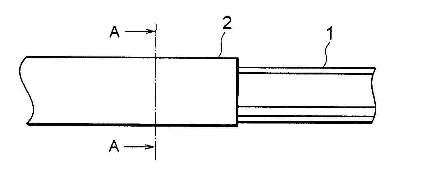
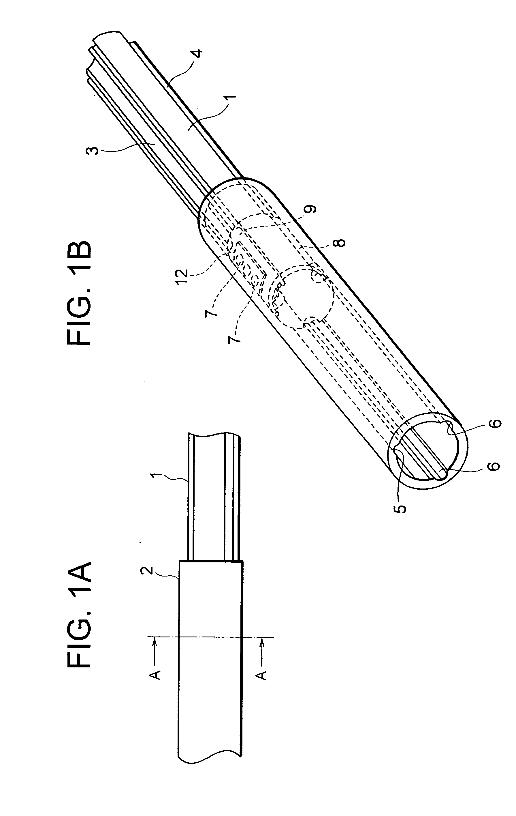
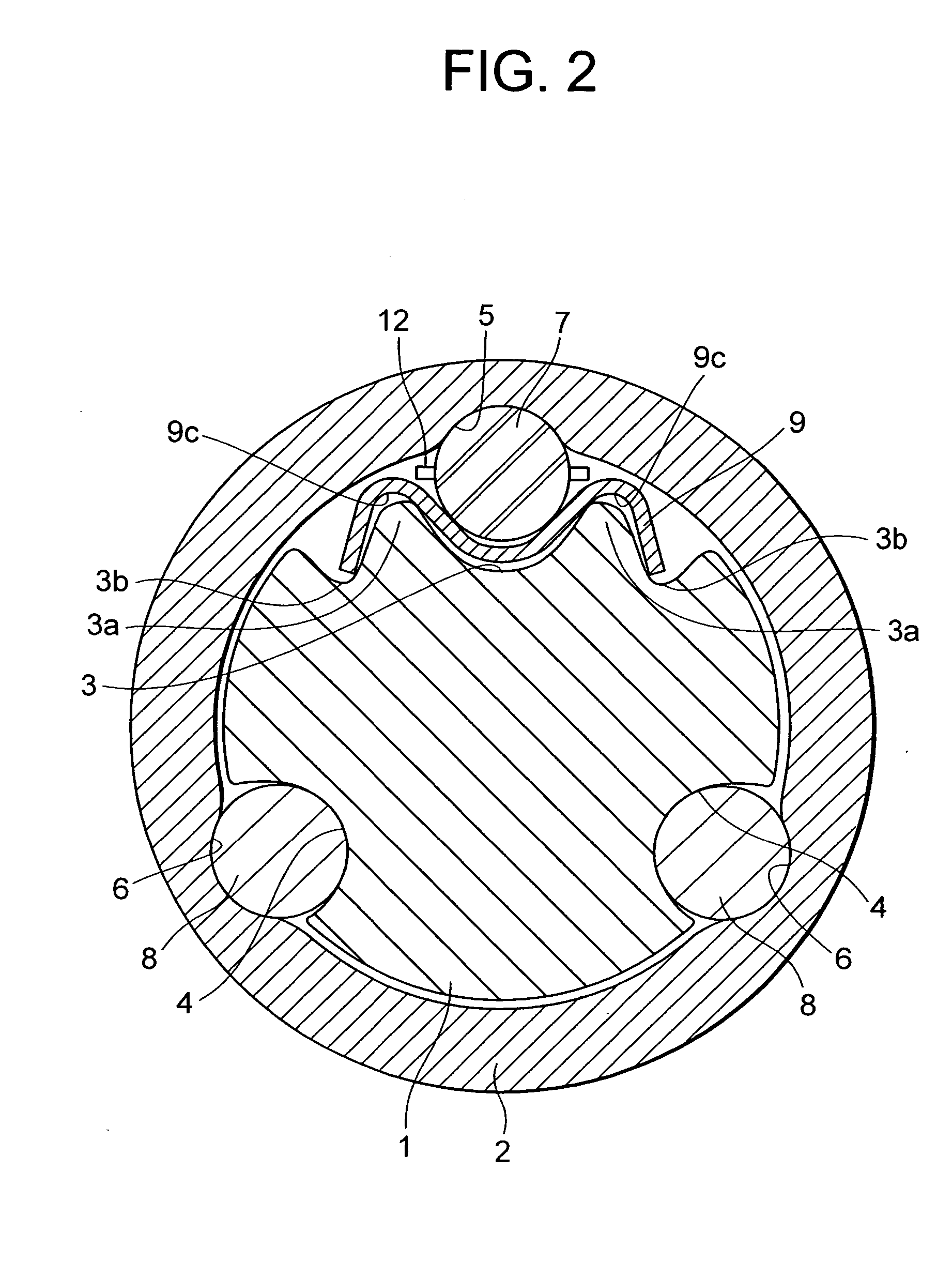
[0069] FIG. 1A is a side view of the telescopic shaft for the vehicle steering in a first embodiment of the present invention. FIG. 1B is a perspective view thereof. FIG. 2 is a cross sectional view taken along the line A-A in FIG. 1A. FIG. 3 is a perspective view showing a state where a male shaft and a female shaft of a telescopic shaft shown in FIG. 1 are separated. FIGS. 4A and 4B are plan views each showing an example of a plate spring. FIG. 4C is an exploded perspective view of the telescopic shaft for the vehicle steering. FIG. 5 is a graph showing a relationship between a stroke of and a slide load of the telescopic shaft for the vehicle steering in the first embodiment.

[0070] As shown in FIG. 1, the telescopic shaft for the vehicle steering (which will hereinafter be simply called the telescopic shaft) is constructed of a male shaft 1 and a female shaft 2 that are so fitted as not to be rotatable but to be slidable on each other.

[0071] As shown in FIG. 2, three lines of axi...

second embodiment

[0105] FIG. 6 is a cross sectional view of the telescopic shaft for the vehicle steering in a second embodiment of the present invention.

[0106] A different point of the second embodiment from the first embodiment is that the first torque transmitting member involves the use of the rigid spherical members 7 in the first embodiment, and by contrast, according to the second embodiment, cylindrical members 14 as the first torque transmitting member are so interposed as to be rollable.

[0107] In the second embodiment, the female shaft 2 is provided with an axial groove 13 of which a bottom surface is formed flat, a plurality of cylindrical members 14 of which axial direction is set orthogonal to the direction in which the male shaft 1 and the female shaft 2 extend, and a holder 15 holds these cylindrical members 14. Other configurations, etc. are the same as those in the first embodiment discussed above.

[0108] The second embodiment also acquires the same features as those in the first emb...

third embodiment

[0109] FIG. 7 is an exploded perspective view of the telescopic shaft for the vehicle steering in a third embodiment of the present invention. FIG. 8 is a perspective view of the holder shown in FIG. 7.

[0110] In the first embodiment (FIGS. 3 and 4) described above, the holder 12 disposed between the male shaft 1 and the female shaft 2 has a plurality of through-holes extending in the axial direction, and holds, e.g., the spherical members 7 as the first torque transmitting members. When the male shaft 1 and the female shaft 2 make the relative movements, the holder 12 also moves corresponding thereto.

[0111] The plurality of spherical members 7 are, however, received respectively in the plurality of through-holes, and hence there might be a possibility in which a speed difference occurs, and the slide resistance is not stabilized.

[0112] Such being the case, according to the third embodiment, for the purpose of stabilizing the slide resistance, as shown in FIGS. 7 and 8, the holder 12...


PUM


Abstract

A vehicle steering telescopic shaft having a male shaft and a female shaft so fitted to each other as not to be rotatable but to be slidable. First torque transmitting members are disposed between the male shaft and the female shaft, and roll when the male shaft and the female shaft make relative movements in axial directions. Elastic members are disposed adjacent in a radial direction to the first torque transmitting members and restrict them when rotated and apply a pre-load to the male shaft and the female shaft through the first torque transmitting members when not rotated. Second torque transmitting members are provided between the male shaft and the female shaft, and slide when the male shaft and the female shaft make the relative movements in the axial directions, and transmit a torque when rotated.

Description

[0001] The present invention relates to a telescopic shaft for a vehicle steering.BACKGROUND ARTS[0002] A steering mechanism unit of an automobile has hitherto involved the use of, as a part of the steering mechanism unit, a telescopic shaft absorbing an axial displacement occurred when the automobile travels and including a male shaft and a female shaft that are spline-fitted to each other in order not to transfer the displacement and vibrations onto a steering wheel. What is required of the telescopic shaft is to reduce backlash noises at the spline portion, to reduce a feeling of backlash on the steering wheel and to reduce a slide resistance when sliding in axial directions.[0003] For these requirements, the spline portion of the male shaft of the telescopic shaft is coated with a nylon layer, and further a grease is applied over a sliding portion, thereby absorbing or relieving metal noises, metal butting sounds, etc. and also reducing the slide resistance and the backlash in a...

Claims


Application Information

Patent Timeline
IPC IPC(8): B62D1/18B62D1/185B62D1/20F16C3/035F16D3/06
CPCB62D1/185B62D1/20F16C3/035F16D3/065F16C29/123F16C2326/24F16C29/007
Inventor YAMADA, YASUHISASHODA, AKIHIROOZAWA, ATSUSHITANIGUCHI, MASATO
Owner NSK LTD
Why Eureka
Try Eureka