
Synthetic resin container with thin wall

a technology of synthetic resin and container, applied in the direction of external fittings, large containers, packaging, etc., can solve the problems of low stability, low stability, and high difficulty in maintaining container shape, and achieve the effect of reducing the risk of rusting, cracking, and easy deformation of the bottom

Inactive Publication Date: 2004-12-16
YOSHINO KOGYOSHO CO LTD
View PDF45 Cites 23 Cited by
  • Summary
  • Abstract
  • Description
  • Claims
  • Application Information

AI Technical Summary

Benefits of technology

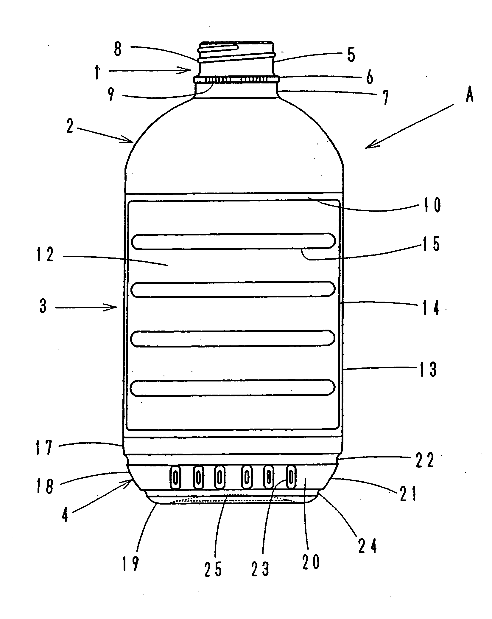
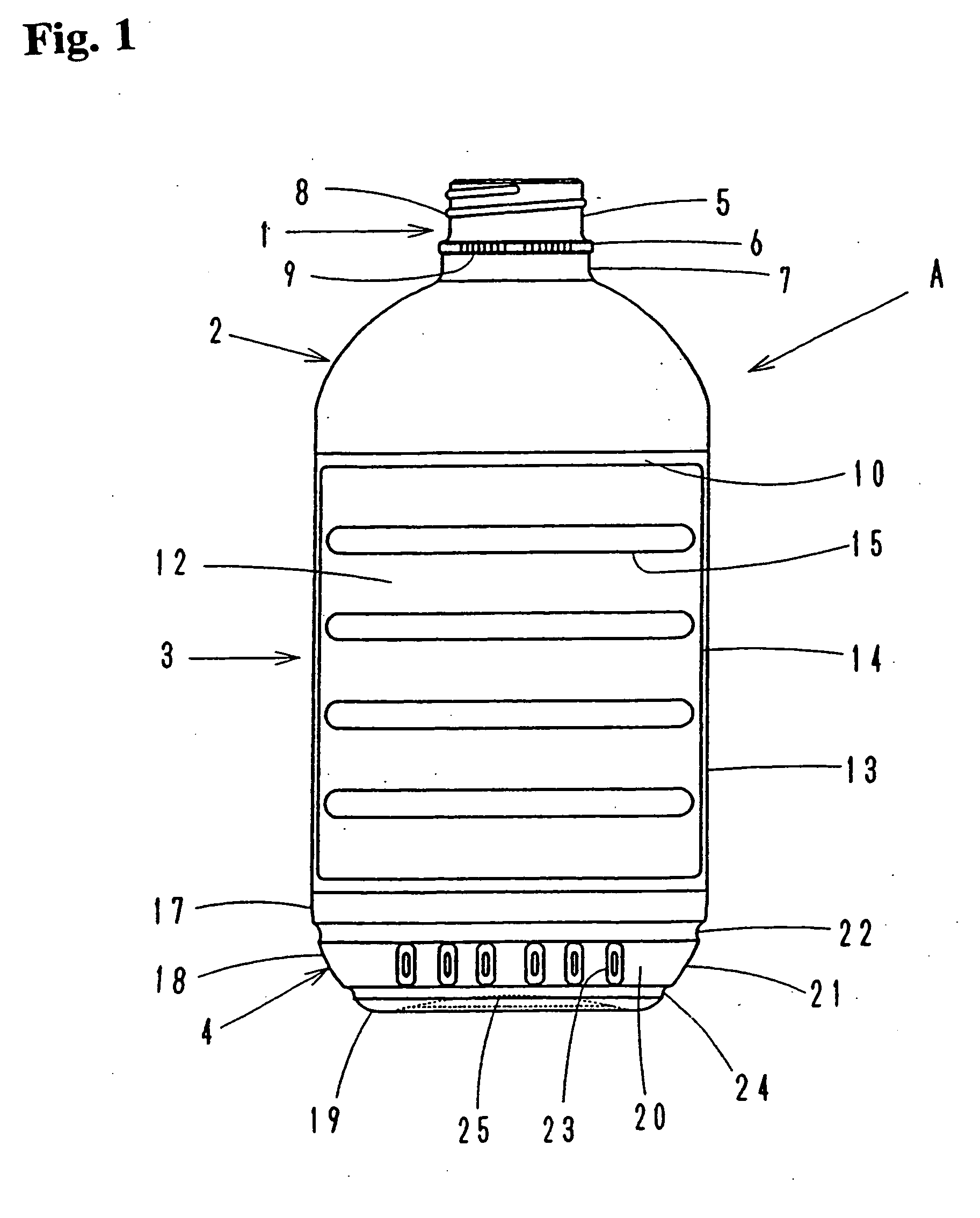
The present invention relates to a synthetic resin thin wall container that can be easily crushed and has improved strength and stability. The container has reinforcing ribs at relevant positions in the body and bottom to maintain its shape while being crushed. The container also has a reinforced neck to reliably open and close with a cap and to prevent deformation when dropped or impacted. The container can be blow molded using PP or PE resin and has a flattened cross section and predetermined height to hold its shape. The container is designed to be easily grasped by hand and can be stacked and transported without losing its shape.

Problems solved by technology

If the container is made to weigh less than 0.05 g / ml for every 1 ml of the liquid contained therein by reducing the wall thickness, it is highly difficult for the container to maintain its shape.
Additionally, there arises a problem that, if the wall thickness of the body portion of the container is reduced, the body loses, if partly, its rigidity and buckling strength.
If the wall thickness of the peripheral wall of the container bottom extending from the body portion is also reduced, the bottom can easily become deformed and / or give rise to cracks when the container is dropped and subjected to impact.
Then, the net result will be that, when the container is filled with liquid, the container body portion becomes deformed and / or the peripheral wall of the container bottom is buckled so that the container will no longer be able to stand upright.
Then, containers can become deformed as a result of collision.
Still additionally, as a result of line contact, containers can become displaced relative to each other and stand obliquely relative to the moving direction to consequently give rise to various problems.
Various problems also arise when blow molded containers are moved from a work station to another if the wall thickness of the shoulder portion is reduced unless the neck portion is improved and / or reinforced.
There also arises a problem that the container cannot be grasped by hand with the neck ring thereof in use.
Finally, it is highly difficult to close the container with the cap while holding it with hand because the shoulder portion has a thin wall thickness.

Method used


Image

  • Synthetic resin container with thin wall
  • Synthetic resin container with thin wall
  • Synthetic resin container with thin wall

Examples


first modified embodiment

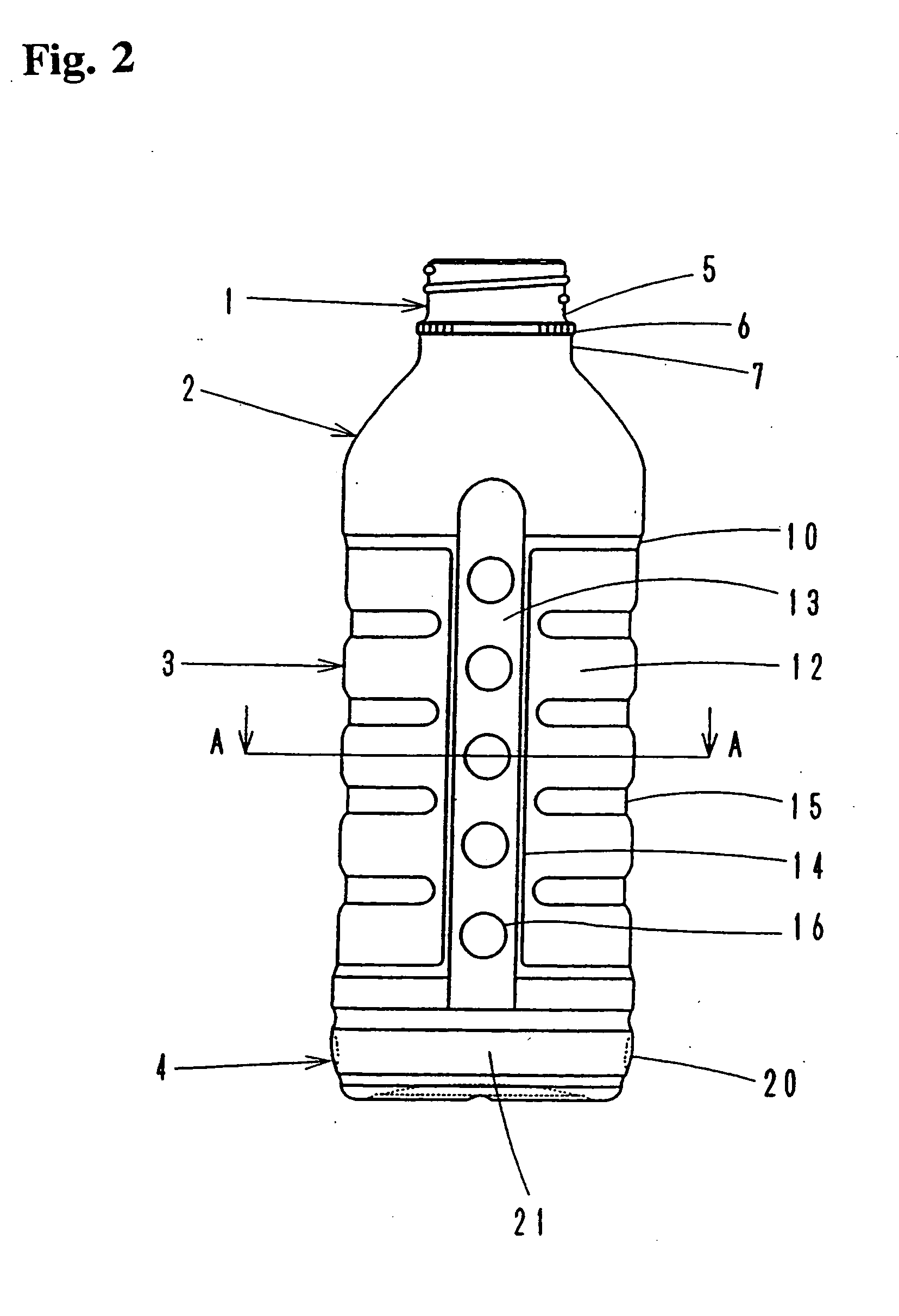
[0089] In the first modified embodiment, the body is modified. Although each of the side walls is provided on the surface thereof with circular reinforcement recesses 16 in the above embodiment, any of the reinforcements as shown in FIG. 7 may be used for the purpose of the invention.

[0090] FIG. 7a shows square recesses 16a having flat bottom.

[0091] FIG. 7b shows transversally extending recessed ribs 16.

[0092] FIG. 7c shows square recesses 16c having flat bottom with additional X-shaped projecting ribs 16d.

[0093] FIG. 7d shows X-shaped recesses 16e or X-shaped projecting ribs 16f. In case of the X-shaped projected ribs 16f, surfaces of the ribs are contacted one another in surface-to-surface, so as to provide the advantage same as that of the above described embodiment.

[0094] In FIG. 7e shows a recessed rib having a zigzag profile and extending longitudinally.

[0095] Each of these reinforcements provides the advantage same as described above to the side wall.

[0096] [2.sup.nd Embodime...

second modified embodiment

[0097] This second modified embodiment is obtained by modifying the side walls of the above embodiment.

[0098] More specifically, the side walls of the body of this embodiment differ from those of the above embodiment, although the neck, the shoulder and the bottom as well as the cross section of the body and the configuration of the front and rear walls are same as their counterparts of the above embodiment. Therefore, in FIGS. 8 and 9 that illustrate this modified embodiment, they are denoted respectively by the same reference numerals, each of which is accompanied by suffix a and will be described only briefly below particularly in terms of the side walls.

[0099] Referring to FIG. 8, the blow molded container "Aa" comprises a neck 1a, a shoulder 2a, a body 3a and a bottom 4a.

[0100] As in the case of the above embodiment, the body 3a includes front and rear walls 12a and side walls 30.

[0101] Each of the side walls 30 comprises an edge section 31 having a predetermined width and runn...

third modified embodiment

[0109] Now, a third modified embodiment obtained by modifying the front and rear walls of the body will be discussed below.

[0110] Since the neck, the shoulder and the bottom as well as the cross section of the body are same as their counterparts of the above embodiment, they are denoted respectively by the same reference numerals which are accompanied by suffix b in FIGS. 10 through 12. This embodiment will be described only briefly below particularly in terms of the front an drear walls.

[0111] As illustrated in FIGS. 10 through 12, the body 3b comprises front and rear walls 40 including a front wall 40a and a rear wall 40b, each of which shows an elliptic cross section, and side walls 41. Each of the side walls 41 is a vertical plane, and intersects the elliptic cross section of the front and rear walls 40. An upper end of each of reaches to the shoulder 2b. Lateral edges of the side walls 41 and corresponding lateral edges of the front and rear walls 40 are connected through narro...


PUM


Abstract

A container has a body which comprises front end rear walls, and the side walls. Each of the front and rear walls has an elliptic cross section, and is provided with a lateral recess. Each of the side walls is a vertical plan which intersects the elliptic cross section of the front and rear walls, and is provided with a plurality of reinforcements. The container has a bottom which comprises a peripheral wall connected to the body and a bottom wall. The peripheral wall comprises slightly inclined front and rear walls, and side walls inclined by a predetermined angle. The peripheral wall is provided with a reinforcing rib.

Description

[0001] 1. Field of the Invention[0002] This invention relates to a synthetic resin thin wall container and, more particularly, it relates to a synthetic resin thin wall container that is reinforced but easily crushable and has an improved profile at the neck, body and bottom.[0003] 2. Related Background Art[0004] In recent years, it has been encouraged to save plastic materials for molded products and recycle plastic products from the viewpoint of environmental protection. Efforts have been paid to provide thin wall containers so that waste containers may be crushed and collected. Thin wall containers that can be easily crushed by hand are already well known.[0005] However, a known thin wall container weighs 0.065 g / ml for every 1 ml of the liquid contained therein if the container is made of polypropylene (PP). In other words, resin has to be used by 32.5 g to form a container with a capacity for containing 500 ml of liquid. If the container is made to weigh less than 0.05 g / ml for...

Claims


Application Information

Patent Timeline
Patent Type & Authority Applications(United States)
IPC IPC(8): B65D1/02
CPCB65D1/0223B65D1/0276B65D2501/0027B65D2501/0036B65D2501/0081B65D1/42
Inventor AKIYAMA, YOSHIOKOSHIO, SHUICHIYONEYAMA, MASASHITOKUDA, HIROAKITANABE, SHOJITOMIYAMA, SHIGERUYONEYAMA, SHIGERU
Owner YOSHINO KOGYOSHO CO LTD
Learn More