Method of fabricating a magnetic coder device, and the device obtained thereby

a magnetic coder and coder technology, applied in auxillary shaping apparatus, sensing output conversion, resilient suspensions, etc., can solve problems such as failure to achieve maximum amplitude magnetization and faulty magnetic coding, and achieve the effect of improving coding density and improving operation

Inactive Publication Date: 2004-12-16
HUTCHINSON SA
View PDF17 Cites 8 Cited by
  • Summary
  • Abstract
  • Description
  • Claims
  • Application Information

AI Technical Summary

Benefits of technology

[0004] An object of the invention is to improve that technique for fabricating a magnetic coder device both to improve its operation and to improve the coding density that can be achieved.
[0005] To this end, the invention provides a method of fabricating a magnetic coder device, the method being of the type consisting in making a mixture of ferromagnetic particles or ferrites in a matrix, in molding the matrix, and in subjecting the molded matrix to a magnetic field so as to obtain a continuous alternation of north and south magnetic poles, which method consists in using a matrix having viscosity that is sufficiently low to enable the ferrites to migrate, in applying a magnetic field during the molding operation while maintaining the matrix at a given temperature in order to reduce its viscosity and thereby making it easier to cause the ferromagnetic particles to migrate and become oriented in their direction of easy magnetization, and to obtain discontinuous shapes having high particle concentration, and in suddenly cooling the matrix while the magnetic field is maintained so as to freeze the particles in the matrix.
[0007] Thus, by applying the method of the invention, the migration and the orientation of ferromagnetic particles under the action of a magnetic field is controlled both in amplitude and in distribution of field lines in space, in a matrix of viscosity that is sufficiently low to allow the ferromagnetic particles to migrate, thus making it possible to impart geometrical shapes that are discontinuous, with a high concentration of ferromagnetic particles.
[0008] Zones are thus obtained that are empty of ferromagnetic particles, thus making it possible to separate poles and to avoid faulty magnetic coding as can be caused by large particles or clusters of particles, and furthermore using a magnetic field to orient the magnetic particles ensues that induction is optimized since the particles become oriented in their direction of easy magnetization.

Problems solved by technology

That technique of fabricating an angular coder gasket presents the particular drawback of running the risk of presenting large ferries or ferrite masses which, when they are ill-positioned, lead to faulty magnetic coding.
Furthermore, mechanically orienting the ferrites and then performing the operation of molding the matrix does not make it possible to achieve magnetization of maximum amplitude, given the magnetization values of ferrites and the ferrite content in the matrix, since certain particles are not oriented in their easy magnetization direction.

Method used


Image

  • Method of fabricating a magnetic coder device, and the device obtained thereby
  • Method of fabricating a magnetic coder device, and the device obtained thereby
  • Method of fabricating a magnetic coder device, and the device obtained thereby

Examples


Embodiment Construction

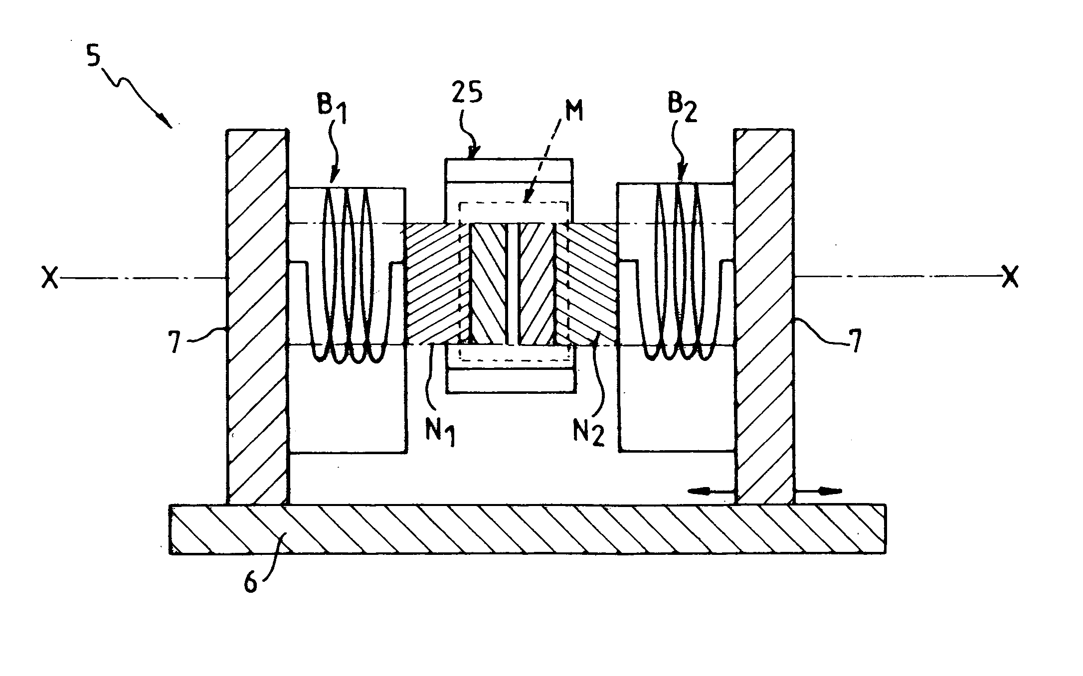
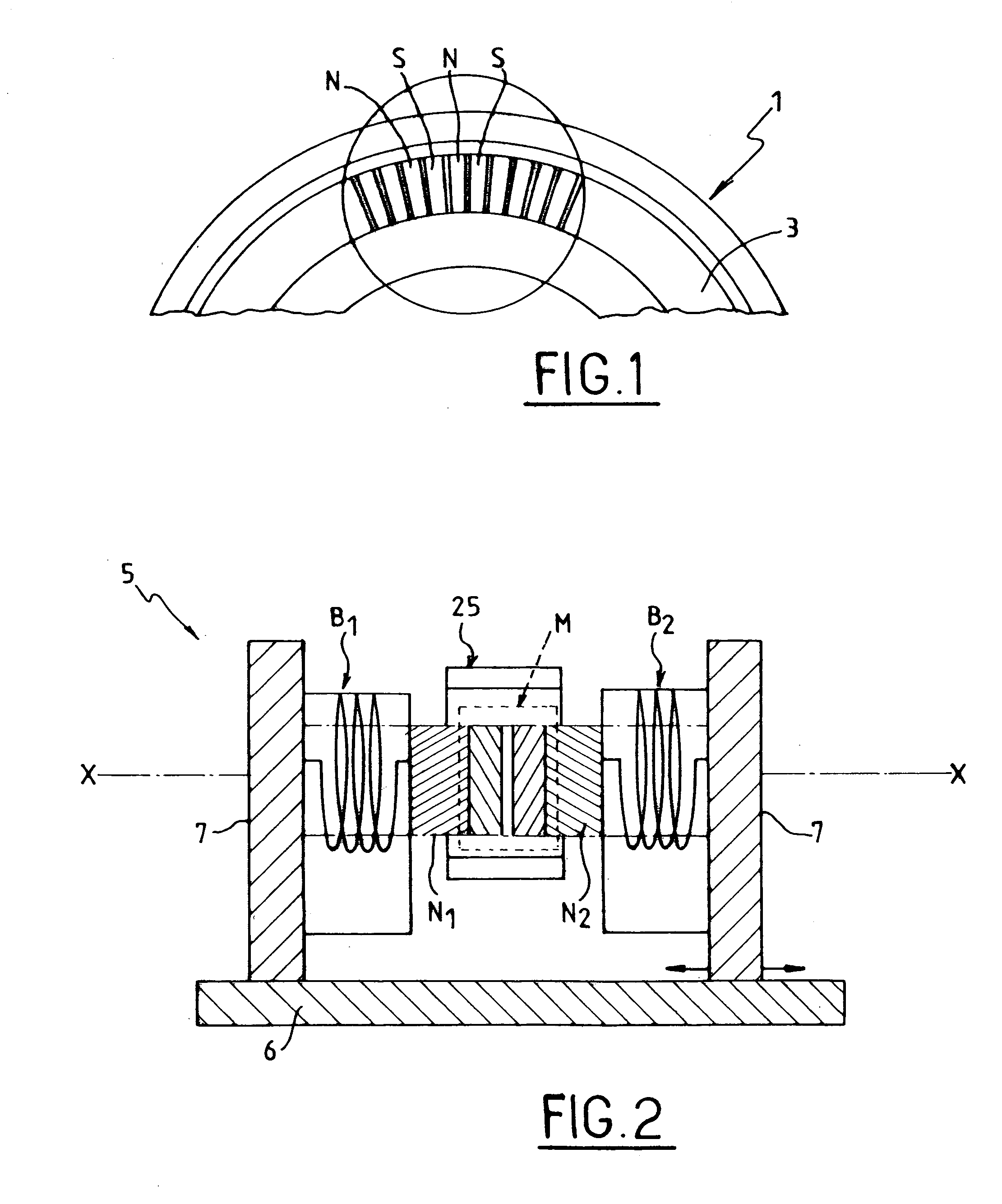
[0019] FIG. 1 shows a portion of a magnetic coder device such as an angle coder gasket 1 of annular shape which presents alternating north and south poles. These north and south poles are obtained by mixing ferromagnetic particles in an elastomer matrix 3, molding the matrix, and then applying a magnetic field, with such a prior art method presenting the drawbacks mentioned in the introduction.

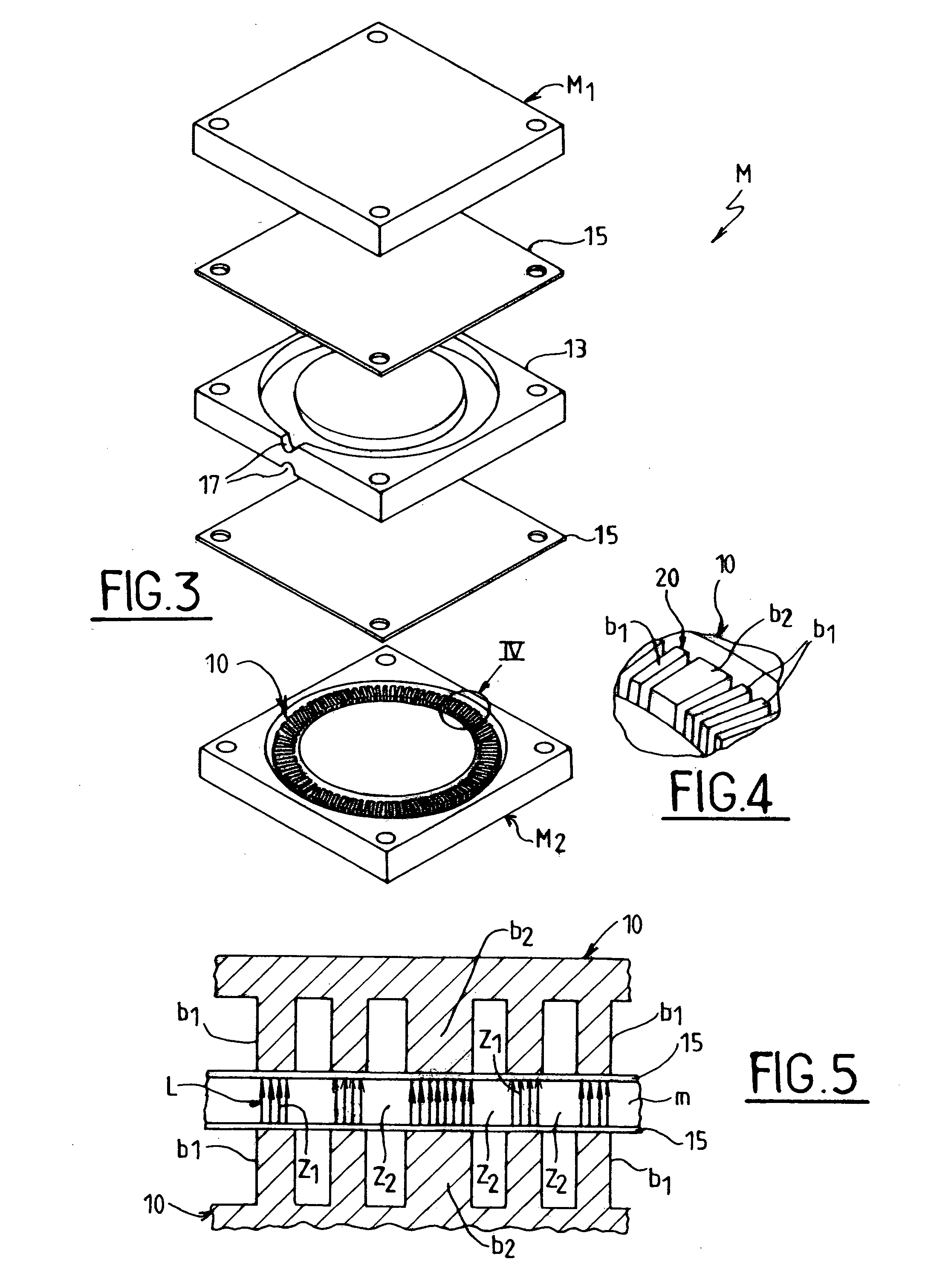
[0020] In contrast, the method of the invention consists in making a mixture of ferromagnetic particles in a matrix of a material that presents viscosity that is sufficiently low, e.g. less than 500 Pa.s, to ensure that the particles can migrate in the matrix and also that they can become oriented along their direction of easy magnetization under the action of a magnetic field that is applied during the operation of molding the matrix. By way of example, the matrix may be made of an elastomer material or a thermoplastic elastomer.

[0021] In general, when implementing the method, a matrix is obt...


PUM

PropertyMeasurementUnit
viscosityaaaaaaaaaa
temperatureaaaaaaaaaa
diameteraaaaaaaaaa

Abstract

A method of fabricating a magnetic coder device, the method being of the type consisting in making a mixture of ferromagnetic particles or ferrites in a matrix, in molding the matrix, and in subjecting the molded matrix to a magnetic field so as to obtain a continuous alternation of north and south magnetic poles, which method consists in using a matrix having viscosity that is sufficiently low to enable the ferrites to migrate, in applying a magnetic field during the molding operation while maintaining the matrix at a given temperature in order to reduce its viscosity and thereby making it easier to cause the ferromagnetic particles to migrate and become oriented in their direction of easy magnetization, and to obtain discontinuous shapes having high particle concentration, and in suddenly cooling the matrix while the magnetic field is maintained so as to freeze the particles in the matrix.

Description

[0001] The invention relates to a method of fabricating a magnetic coder device, and in particular an angle coder gasket suitable for use in particular in applications for measuring angular speeds in the automobile industry, for example.[0002] In an angle coder gasket that is already known, ferromagnetic fillers or ferrites are uniformly dispersed in an elastomer matrix which is molded on a receiving support of annular shape, for example. During the operation of being mixed with the elastomer matrix, the ferrites are mechanically oriented into their easy magnetization direction, without being able to migrate within the matrix. Mechanical orientation is obtained, for example, by subjecting the matrix to shear operations. Thereafter, the matrix is molded and is subjected to the action of a magnetic field so as to magnetize the ferrites and thus obtain a continuous alternation of north and south magnetic poles.[0003] That technique of fabricating an angular coder gasket presents the pa...

Claims


Application Information

Patent Timeline
Patent Type & Authority Applications(United States)
IPC IPC(8): G01D5/245F02D35/00G01D5/14G01D5/16G01P3/487H01F13/00H01F41/02
CPCG01D5/145G01P3/487H01F13/003H01F41/028G01D2205/80
Inventor SAUTIER, PASCALARGY, GILLES
Owner HUTCHINSON SA
Why Eureka
Try Eureka