Heat exchanger device

a heat exchanger and heat exchanger technology, applied in the field of heat exchanger devices, can solve the problems of sucking up secondary air, long flame, and relative long flame which leaves the burner

Inactive Publication Date: 2004-12-23
CONVOTHERM ELEKTROGERATE
View PDF3 Cites 6 Cited by
  • Summary
  • Abstract
  • Description
  • Claims
  • Application Information

AI Technical Summary

Benefits of technology

[0007] In this design, the gas / air mixture is premixed ready for combustion and conveyed into the burner. Accordingly, the dual air induction, namely the induction of primary air at the venturi pipe and the induction of secondary air at the beginning of the flame and of the heat exchanger pipe, as required in the prior art device, is rendered superfluous by the present invention. The present invention therefore avoids the main cause of noise production in the prior art devices. Since the burner according to the invention is also connected to the heat exchanger pipe in a gastight manner, it is situated in a sealed combustion chamber which further damps the production of noise which arises during combustion. Since only the coordination of the gas and combustion air in terms of volume needs monitoring, the outlay for the regulation and therefore for the regulating device are reduced by use of the mixing device. The complete pre-mixing of the gas / air mixture required for combustion permits the formation of a plurality of small flames instead of one large flame, thus making it possible not only to damp the production of noise, but also to realize a greater power for the burner relative to the space taken up.
[0014] The heat exchanger device may include two fastening points to the apparatus for the heat treatment. One fastening point is formed between a wall in the cooking appliance and combustion chamber and the second fastening point is formed between that end of the heat exchanger pipe which emerges from the apparatus for the heat treatment and a housing wall of the apparatus for the heat treatment. In this arrangement, the heat exchanger device is in a position to allow the thermal expansions which occur during operation in a largely stress-free manner. It is particularly advantageous if the fastening points are arranged in close vicinity to each other, as a result of which the entire heat exchanger device can follow virtually without restriction the thermal expansions which occur.

Problems solved by technology

In this case, the burner is arranged upstream of the heat exchanger pipe, with the result that the relatively long flame which leaves the burner penetrates into the heat exchanger pipe and in the process also sucks up secondary air.
A disadvantage of this design is the fact that a very long flame is produced which requires a first, rectilinear section of the heat exchanger pipe, if this flame is to be formed in an exact manner.
In addition, a considerable noise is produced at the two suction points for air.
When this apparatus is used for the heat treatment of foodstuffs, the noise causes a considerable annoyance in the rooms where appliances of this type are installed.
Furthermore, this type of burner design requires continuous pressure monitoring of both the air pressure and the gas pressure and monitoring of the quantities fed in, which necessitates an extensive regulating device.
However, there may be spatially induced conditions which necessitate a different formation of the flames.

Method used


Image

  • Heat exchanger device
  • Heat exchanger device
  • Heat exchanger device

Examples


Embodiment Construction

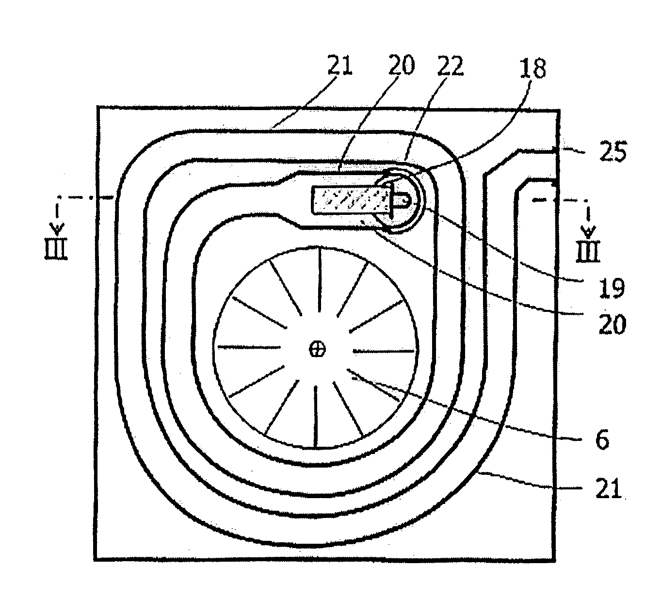
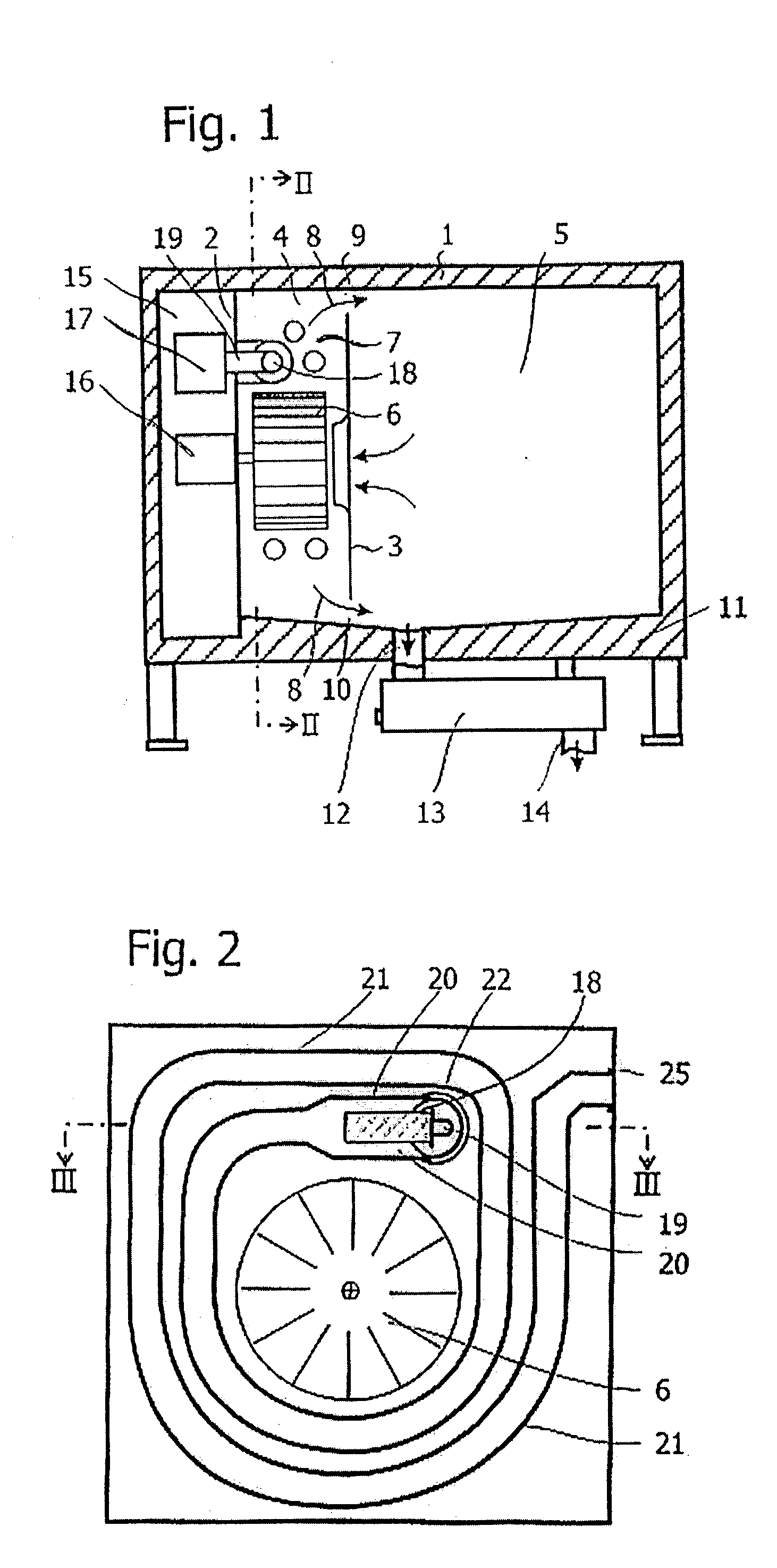
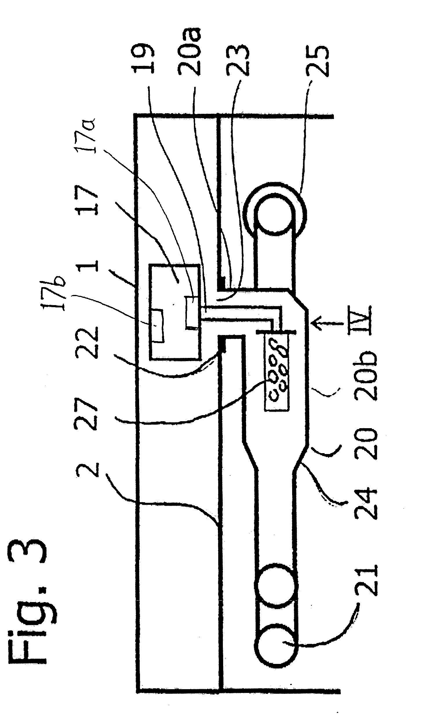
[0022] An apparatus for the heat treatment of foodstuffs is referred to as a cooking appliance in the following text. The cooking appliance according to the present invention has a housing 1 which includes a customary front covering (not illustrated) and door. The housing further includes a partition 2 which divides the housing into sections which are separated from one another in a sealed manner. In the one section, a further partition 3 separates a space 4 from a space 5. The space 4 accommodates a fan wheel 6 and a heat exchanger device 7 while the space 5 is used as a cooking space for receiving the foodstuffs to be treated. Steam is introduced into the space 4 by a steam generator (not illustrated), thus producing a steam / air mixture which is blown by the fan wheel 6 in accordance with the arrows 8 through slots 9 and 10 in the partition 3 into the cooking space. This steam / air mixture is heated up by the heat exchanger device 7. A floor 11 of the cooking space 5 opens into an ...


PUM


Abstract

A heat exchanger device for a cooking appliance includes a burner arranged in a combustion chamber. The burner is connected by a feeding pipe to a mixing device which prepares a gas / air mixture necessary for the combustion and feeds it to the burner. The mixing device is connected to the burner in a gastight manner additional air is prevented from flowing in. The combustion chamber is formed by an enlargement of a heat exchanger pipe which, starting from the combustion chamber, spirally surrounds the fan wheel which provides forced circulation of the treatment medium. The heat exchanger pipe is also wound around the combustion chamber.

Description

[0001] 1. Field of the Invention[0002] The present invention relates to a heat exchanger device in a gas-heated apparatuses used for the heat treatment of foodstuffs, the heat exchanger device having a fan wheel for the forced circulation of a treatment medium, a gas burner and at least one heat exchanger pipe surrounding the fan wheel.[0003] 2. Description of the Related Art[0004] A heat exchanger apparatus of this type is disclosed in EP 0 526 768 B1. The burner therein is designed as a Bunsen burner and comprises a venturi pipe into which gas from a gas nozzle is blown. Air is entrained in the venturi pipe on account of the distance between the venturi pipe and the gas nozzle, so that a certain premixing of air and gas occurs. In this case, the burner is arranged upstream of the heat exchanger pipe, with the result that the relatively long flame which leaves the burner penetrates into the heat exchanger pipe and in the process also sucks up secondary air. A disadvantage of this d...

Claims


Application Information

Patent Timeline
Patent Type & Authority Applications(United States)
IPC IPC(8): F24C15/32
CPCF24C15/322
Inventor SMITS, STANGUMIENNY, GERDRIEFENSTEIN, LUTZ
Owner CONVOTHERM ELEKTROGERATE
Why Eureka
Try Eureka