Optical system for a gas measurement system

a technology of optical aperture and gas measurement system, which is applied in the field of gas measurement system, can solve the problems of hampered progress in improving device performance and seamless interchangeability of sample cells with different sized optical apertures

Active Publication Date: 2004-12-23
RIC INVESTMENTS LLC
View PDF10 Cites 56 Cited by
  • Summary
  • Abstract
  • Description
  • Claims
  • Application Information

AI Technical Summary

Problems solved by technology

The observed differences between the different types of sample cells that are used with the same transducer have been termed the "bias" problem...

Method used


Image

  • Optical system for a gas measurement system
  • Optical system for a gas measurement system
  • Optical system for a gas measurement system

Examples


Embodiment Construction

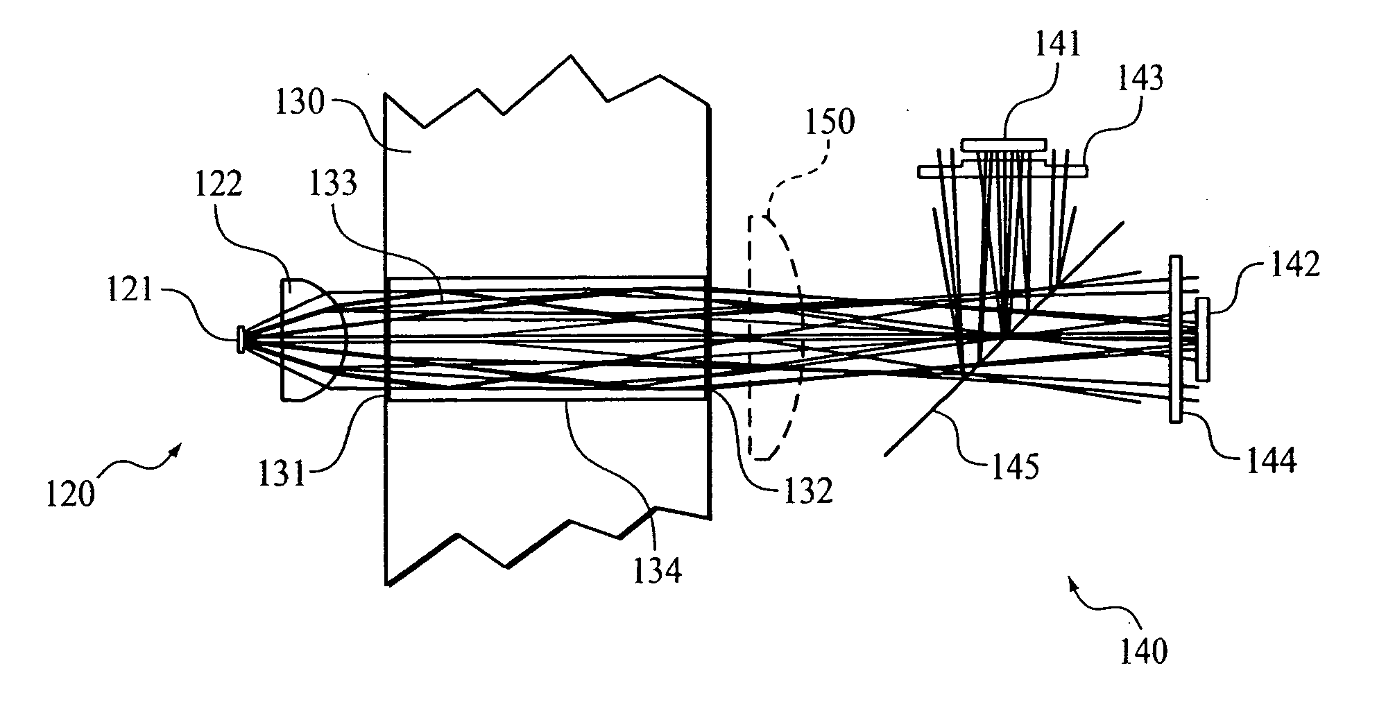
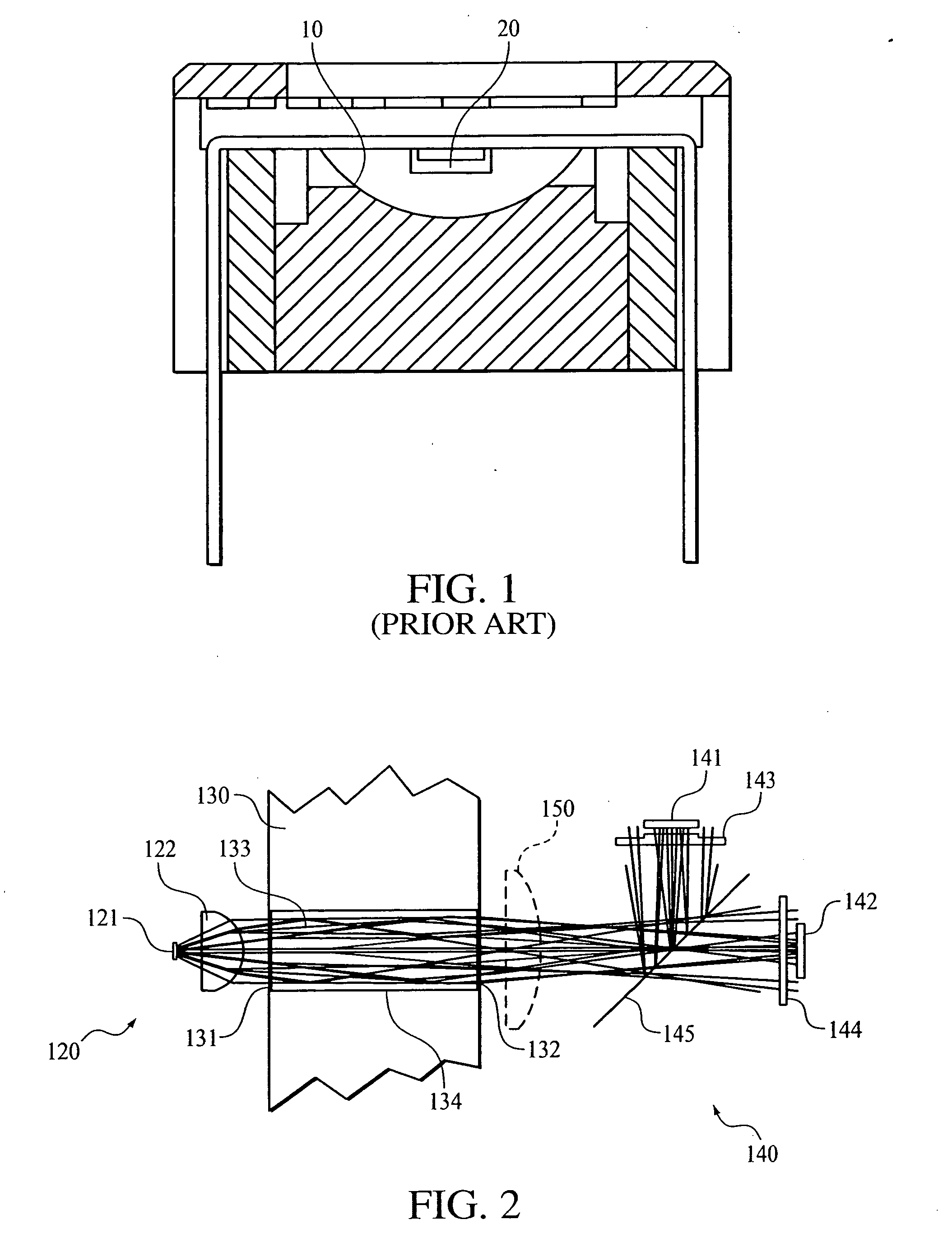
[0034] With the development of gas analyzers using different sized sample cells having different optical apertures, such as the two different sample cell configurations illustrated in FIG. 5A-5C and 6A-6C, a need exists to reduce the source energy lost in the sample cell and the associated loss in signal level measured by the radiation detector. The present inventors observed that the desire to use different sample cell configurations interchangeably with the same transducer raised two measurement problems: a reduction in the infrared radiation received by the detectors, i.e., source efficiency, for small aperture sample cells, and a shift in data / reference ratio, previously referred to as the "bias" problem, when different airway apertures are used.

[0035] In investigating the cause of the "bias", it was determined that different sized apertures alter the mix of ray angles in the bundle of rays received at the NDIR detector assembly, which is comprised of a narrow band filter and a ...


PUM


Abstract

An improved optical configuration for use in a gas monitoring system. The optical system uses a high numerical aperture lens that maximizes capture of relatively large angle rays, thereby increasing the measured signal at the infrared radiation detector. In one embodiment of the present invention, a half-ball-type lens is provided proximal to the infrared radiation source in the gas measurement system. To further increase the measured signal at the infrared radiation detector and allow more efficient capture of the larger angle rays, materials that are reflective in the infrared band of interest are used, so that the walls of the sample cell act as a hollow light pipe.

Description

[0001] This application claims priority under 35 U.S.C. .sctn. 119(e) from provisional U.S. patent application No. 60 / 452,656 filed Mar. 7, 2003, the contents of which are incorporated herein by reference.[0002] 1. Field of the Invention[0003] The present invention pertains to a gas measurement system, and, in particular, to a gas measurement system having an improved optical system, and to a method of using such a system.[0004] 2. Description of the Related Art[0005] It is well-known to those skilled in the art that non-dispersive infrared (NDIR) type gas analyzers operate on the principle that the concentration of specific gases, such as carbon dioxide, nitrous oxide, and anesthetic agents, can be determined by (a) directing infrared radiation from an infrared emitter through a sample of a gaseous mixture, (b) filtering this infrared radiation to minimize the energy outside the band absorbed by the specific gases, (c) measuring the radiation impinging upon an infrared radiation de...

Claims


Application Information

Patent Timeline
IPC IPC(8): A61B5/083G01N21/05G01N21/35
CPCA61B5/083G01N21/05G01N21/3504
Inventor RUSSELL, JAMES T.
Owner RIC INVESTMENTS LLC
Why Eureka
Try Eureka