Reactive power optimization with adaptive excitation control

a technology of excitation control and reactive power, applied in the direction of multiple ac dynamo-electric motor control, electric variable regulation, synchronous motor starters, etc., can solve the problems of large amount of electrical power, high cost of imported power, and inability to supervise or monitor the overall power system at the plant or facility. , to achieve the effect of power control, saving energy and saving energy in the facility

Active Publication Date: 2004-12-23
SAUDI ARABIAN OIL CO
View PDF15 Cites 42 Cited by
  • Summary
  • Abstract
  • Description
  • Claims
  • Application Information

AI Technical Summary

Benefits of technology

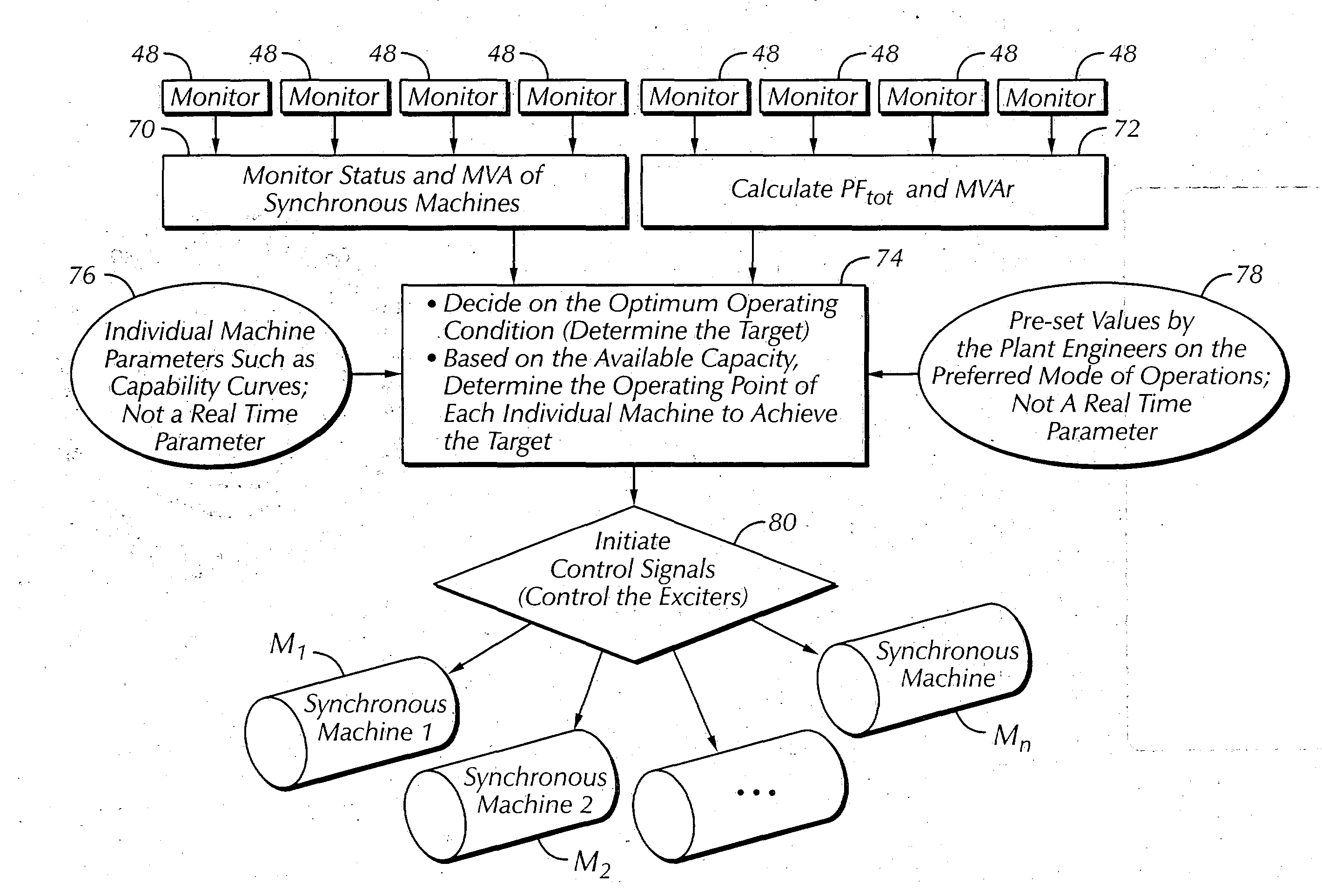
[0051] Decide on the best operation mode to bring the plant total power factor as close to unity as possible, without compromising system stability and synchronous motor capability curves.
[0071] With the present invention, the voltage drop in the power system for the plant during motor starts can be controlled and provide an improvement of the system stiffness before starting other motors in the system. This is done by overexciting the operating synchronous machines to their operating limits before the other motors are started. The control logic of the adaptive excitation control system C is triggered to over excite the then operating or online synchronous machines M.sub.1, M.sub.2 . . . M.sub.n a few seconds before the motor start event.

Problems solved by technology

Efficient usage of electrical energy has become a matter of increasing concern, and electrical energy costs often are an important factor in overall expenses of an industrial plant or other facility driven by electrical power.
However, so far as is known, traditional methods of power factor improvement have not supervised or monitored the overall power system at the plant or facility of interest.
However, these motors have operated in industrial plants at a constant power factor, without considering either overall system performance or dynamic changes in the plant's power distribution system during operation.
As a result, considerable amounts of electrical power beyond that actually needed for the actual plant electrical load have been required to be imported to meet actual load requirements.
The imported power was costly, and often was at even higher or premium rates when imported at times of peak demand.

Method used


Image

  • Reactive power optimization with adaptive excitation control
  • Reactive power optimization with adaptive excitation control
  • Reactive power optimization with adaptive excitation control

Examples


example 2

Leading Power Factor at 50% Load

[0081] Loads in this example were similar to Example 1. The synchronous machines were momentarily over excited to support the bus voltage during the start of the induction motor. The following shows the system condition just before the start of the induction motor.

2 KVA kW kVAR PF Total 47.2 20 -42.8 (Gen) 0.4 Leading Incoming Power M.sub.1 24.3 9.6 -22.3 (Gen) 0.4 Leading Incoming Power M.sub.2 22.9 10.3 -20.5 (Gen) 0.4 Leading

[0082] The induction motor M.sub.x was then started. FIG. 15 shows line voltage (V.sub.bc and line current (I.sub.b) trending over time. In this case the voltage dropped to only 4% of the nominal voltage and the acceleration time was 300 msec.

example 3

Lagging Power Factor at 90% Load

[0083] In this example the system is highly loaded and / the power factor of the system was 83% lagging. The power quantities measured before starting the induction motor (Induction 1) are summarized in the following Table.

3 KVA kW kVAR PF Total 42.6 35.4 23.7 -0.83 Incoming Power M.sub.1 23.7 19.8 13.0 -0.83 Incoming Power M.sub.2 18.9 15.6 10.7 -0.83

[0084] The induction motor M.sub.x was then started. FIG. 16 shows line voltage (V.sub.bc) and line current (I.sub.b) trending over time. In this example the voltage dropped to 10% of the nominal voltage and the acceleration time is 358 msec.

example 4

High PF With Synchronous Motors Operating at Unity Power Factor and 90% Load

[0085] In this example the power factor of the system was -98% lagging. The power quantities measured before starting the induction motor are summarized in the following Table.

4 KVA kW Kvar PF Total 37.7 36.8 7.8 -0.98 Incoming Power M.sub.1 20.5 19.9 4.9 -0.97 Incoming Power M.sub.2 17.2 16.9 2.9 -0.98

[0086] The induction motor M.sub.x was then started. FIG. 21 shows line voltage (V.sub.bc) and line current (I.sub.b) trending over time. In this example the voltage dropped to 9% of the nominal voltage and the acceleration time was 350 msec.


PUM


Abstract

Reactive power (VAR) consumption in a power plant or facility having synchronous machines is adaptively controlled in an automated manner. Electrical parameters of the plant are dynamically monitored during plant operation, and the overall plant power system is brought to an optimum operating point under control of a microprocessor-based power measurement system. The microprocessor-based power measurement system adaptively changes the excitation system of synchronous machines in the plant based on results of monitoring. The excitation systems of the synchronous machines may be adjusted to be constant bus voltage, constant reactive power, or constant power factor, according to optimum system performance requirements. The power measurement system also assists in avoiding problems in voltage regulation during increased load demand conditions, such as when starting large electrical motors or energizing large transformers in the system.

Description

BACKGROUND OF INVENTION[0001] 1. Field of Invention[0002] The present invention relates to energy conservation in industrial plants and other facilities. More particularly, the present invention relates to control of reactive power consumption in such plants and facilities.[0003] 2. Description of the Prior Art[0004] It has become a common practice in industrial facilities to pay increased attention to energy conservation programs. Efficient usage of electrical energy has become a matter of increasing concern, and electrical energy costs often are an important factor in overall expenses of an industrial plant or other facility driven by electrical power.[0005] Where electrical power is furnished as alternating current (or AC) power, one way to save energy has been to improve the power factor (PF). As is known, the power factor of alternating current in a system is the ratio of real power to apparent power, or in effect the cosine of the phase angle between voltage and current in the...

Claims


Application Information

Patent Timeline
Patent Type & Authority Applications(United States)
IPC IPC(8): G05F1/70H02P5/74H02P6/00
CPCG05F1/70H02P5/74H02P6/001H02P6/34
Inventor AL-HAMRANI, MAJED
Owner SAUDI ARABIAN OIL CO
Why Eureka
Try Eureka