Wide-angle imaging optical system and wide-angle imaging apparatus surveillance imaging apparatus vehicle-mounted imaging apparatus and projection apparatus using the wide-angle imaging optical system

a wide-angle imaging and optical system technology, applied in the field of wide-angle imaging optical system and wide-angle imaging apparatus surveillance imaging apparatus, can solve the problems of increasing the weight of the optical system, increasing the size of the apparatus, increasing the cost of the apparatus, etc., and achieves the effects of improving aberration correction, simple structure, and long back focal length

Inactive Publication Date: 2004-12-30
PANASONIC CORP
View PDF7 Cites 25 Cited by
  • Summary
  • Abstract
  • Description
  • Claims
  • Application Information

AI Technical Summary

Benefits of technology

0011] To solve the above conventional problems, it is an object of the present invention to provide a wide-angle imaging optical system that can produce a panoramic image covering a maximum horizontal angle of view of 360 degrees as well as an image in the vicinity of the axial direction with a simple structure and has a relatively long back focal length, improved aberration correction, and brightness.

Problems solved by technology

However, a wide-angle imaging optical system using, e.g., a fish-eye lens generally requires many lenses.
Therefore, the weight of the optical system is increased, and the apparatus becomes large and expensive.
Moreover, the generation of chromatic aberration or the like is a problem, and actually this wide-angle imaging optical system is only used for taking pictures with special techniques.
Therefore, a transparent material used for the rotating body is thick, and when the transparent material is resin, it is susceptible to temperature changes and takes longer to be molded.
When the transparent material is glass, particularly aspherical glass, considerable cost is involved in polishing the glass.
Consequently, the master lens becomes large and complicated.

Method used


Image

  • Wide-angle imaging optical system and wide-angle imaging apparatus surveillance imaging apparatus vehicle-mounted imaging apparatus and projection apparatus using the wide-angle imaging optical system
  • Wide-angle imaging optical system and wide-angle imaging apparatus surveillance imaging apparatus vehicle-mounted imaging apparatus and projection apparatus using the wide-angle imaging optical system
  • Wide-angle imaging optical system and wide-angle imaging apparatus surveillance imaging apparatus vehicle-mounted imaging apparatus and projection apparatus using the wide-angle imaging optical system

Examples


example 2

[0288] Example 2 is directed to the wide-angle imaging apparatus in FIG. 34. In Example 2, the focal length fa (mm), brightness Fno, and imaging range (half angle of view) .omega. (.degree.) of the first optical system are as follows:

[0289] fa=1.00, Fno=1.97, and .omega.=30 to 90.degree..

[0290] Table 3 shows numerical values of the first optical system in Example 2.

3TABLE 3 No. rai dai nd .nu.d a1 10.415 -3.40 Reflection surface a2 23.049 3.40 Reflection surface a10 .infin. 0.14 Lens stop plane a11 -1.524 1.19 1.84666 23.8 Cemented lens a12 2.499 1.83 1.72916 54.7 a13 -3.010 0.12 a14 6.699 1.75 1.72916 54.7 a15 -7.383 0.12 a16 4.120 1.75 1.52404 56.4 a17 -25.084 0.34 a18 .infin. 2.0 1.51680 64.2 a19 .infin.

[0291] In Example 2, the focal length fb (mm), brightness Fno, and imaging range (half angle of view) .omega. (.degree.) of the second optical system are as follows:

[0292] fb=0.80, Fno=1.97, and .omega.=0 to 30.degree..

[0293] Table 4 shows numerical values of the second optical sy...

example 3

[0319] Example 3 is directed to the wide-angle imaging apparatus in FIG. 35. In Example 3, the focal length fa (mm), brightness Fno, and imaging range (half angle of view) .omega. (.degree.) of the first optical system are as follows:

[0320] fa=1.00, Fno=2.00, and .omega.=25 to 90.degree..

[0321] Table 5 shows numerical values of the first optical system in Example 3.

5TABLE 5 No. rai dai nd .nu.d a1 12.659 -13.82 Reflection surface a2 28.527 13.82 Reflection surface a10 .infin. 0.38 Lens stop plane a11 -2.662 2.87 1.84665 23.8 Cemented lens a12 3.760 1.52 1.72916 54.7 a13 -4.125 0.08 a14 5.822 0.94 1.72916 54.7 a15 737.670 0.08 a16 3.017 1.13 1.72916 54.7 a17 6.441 0.38 a18 .infin. 2.00 1.51680 64.2 a19 .infin.

[0322] In Example 3, the focal length fb (mm), brightness Fno, and imaging range (half angle of view) .omega. (.degree.) of the second optical system are as follows:

[0323] fb=0.80, Fno=2.00, and .omega.=0 to 25.degree..

[0324] Table 6 shows numerical values of the second optical ...

embodiment 19

[0340] Embodiment 19

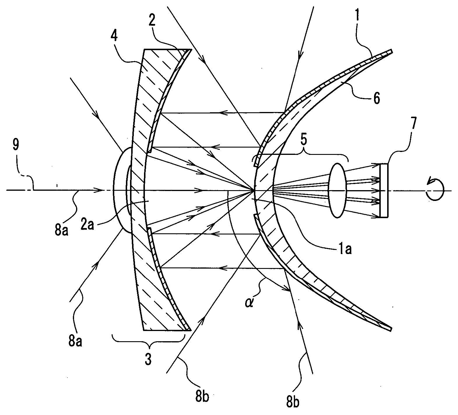
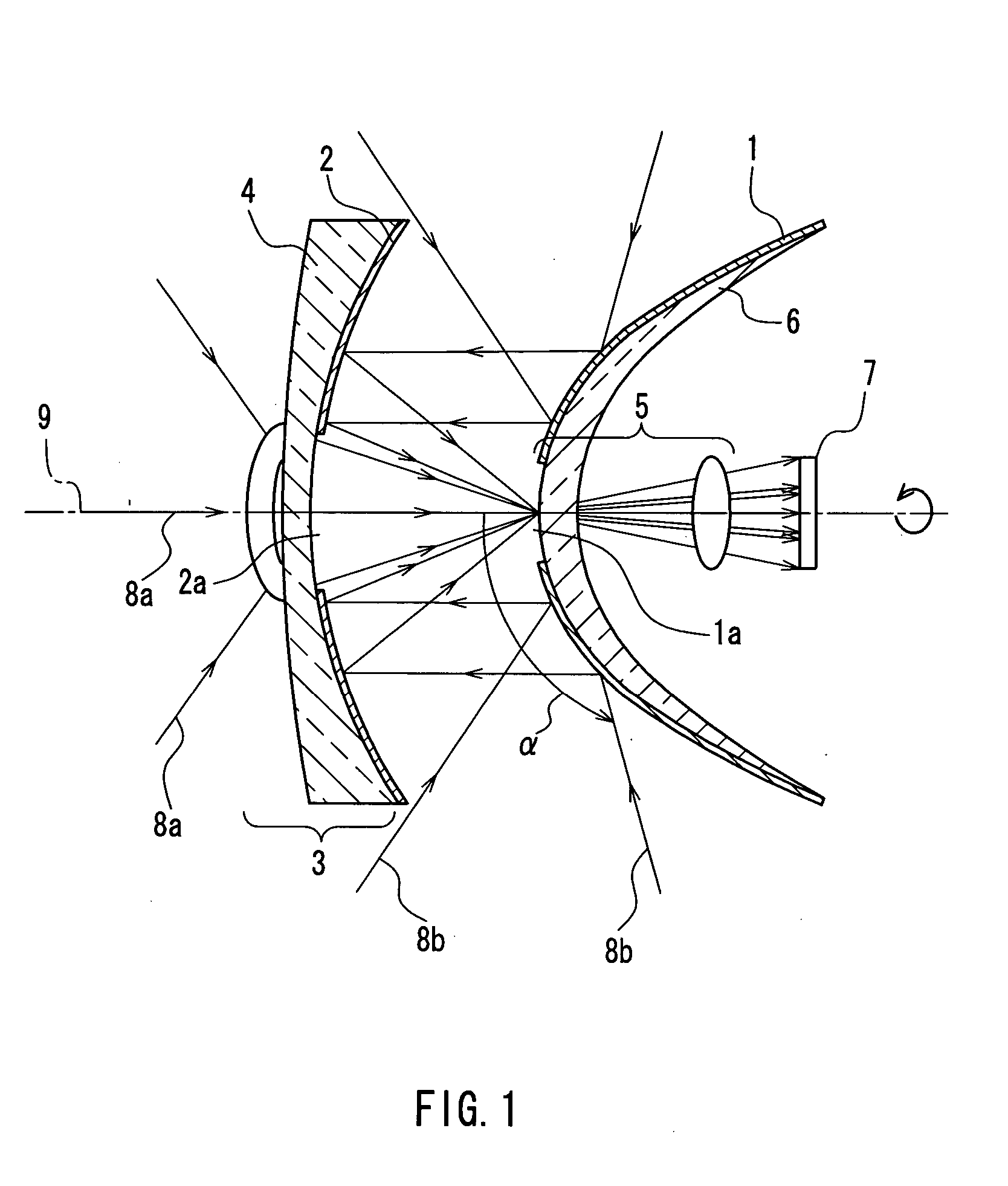
[0341] FIG. 42 shows the combination of a first reflection surface and a second reflection surface and corresponds to a cross-sectional view taken along a plane containing a central axis 9. FIG. 42 only illustrates lenses of the image-forming optical system and first reflection surfaces 221 that are formed integrally with the lenses, and lenses of the refractive optical system and second reflection surfaces 221 that are formed integrally with the lenses, but does not illustrate a third reflection surface, an imaging device, or the like.

[0342] In this configuration, the first reflection surfaces 221 have a convex surface as seen from incident light from the object side, and the second reflection surfaces 222 have a concave surface as seen from the incident light. In FIG. 42, two pairs of reflection surfaces are arranged from side to side. However, half of the pairs can be applied to any of the configurations as shown in FIGS. 1 to 12.


PUM


Abstract

A wide-angle imaging optical system includes a refractive optical system (3), a reflective optical system, and an image-forming optical system (5). The reflective optical system includes a first reflection surface (1) that directly reflects rays of light from an object, and a second reflection surface (2) that reflects rays of light from the first reflection surface (1). An open portion is provided between the first reflection surface (1) and the second reflection surface (2), and rays of light from the object enter the open portion. A light-transmitting portion (2a) is provided in the second reflection surface (2) and transmits rays of light that have entered the refractive optical system (3). An aperture (1a) is provided in the first reflection surface (1) and allows rays of light from the second reflection surface (2) and the refractive optical system (3) to enter the image-forming optical system (5).

Description

[0001] The present invention relates to a wide-angle imaging apparatus that can produce a panoramic image covering an ultra-wide range by using the combination of reflection surfaces and the combination of lenses.[0002] Various research and development have been conducted on a wide-angle imaging apparatus to efficiently produce an image of an object in a large area. One example is the development of a wide-angle camera with a fish-eye lens.[0003] JP 10(1998)-54939 A (REFLECTION TYPE VIEWING ANGLE CONVERTING OPTICAL DEVICE AND OPTICAL SYSTEM USING THE DEVICE) proposes a system that produces an image of a wide visual field by variously changing the shapes of three mirror surfaces arranged opposite to each other. JP 2000-4383 A (MULTIDIRECTIONAL IMAGE TAKING-IN DEVICE) proposes an optical system that produces a counter image inside a normal image by using a shaft of a panoramic image block as a lens.[0004] JP 2001-94839 A (WIDE VISUAL FIELD IMAGE PICKUP DEVICE AND WIDE VISUAL FIELD IMA...

Claims


Application Information

Patent Timeline
Patent Type & Authority Applications(United States)
IPC IPC(8): G02B13/06G02B17/06G02B17/08G02B27/00
CPCG02B13/06G02B17/061G02B17/0694G02B27/0018H04N23/00
Inventor MATSUKI, DAIZABUROYOSHIKAWA, MOTONOBUYAMAMOTO, YOSHIHARU
Owner PANASONIC CORP
Why Eureka
Try Eureka