Apparatus for monitoring tire pressure

a technology for monitoring equipment and tires, applied in vehicle tyre testing, instruments, roads, etc., can solve problems such as sensitivity, complication in accessing information, and indirect tire pressure monitoring systems that may not identify critical combinations of multiple under-inflated tires, so as to achieve the effect of easy application and removal of tires

Inactive Publication Date: 2005-01-06
HARALAMPU STEPHEN GEORGE +3
View PDF1 Cites 36 Cited by
  • Summary
  • Abstract
  • Description
  • Claims
  • Application Information

AI Technical Summary

Benefits of technology

It is an object of the present invention to provide a tire pressure mon

Problems solved by technology

Although this system has the advantage of using equipment already installed on many vehicles, there are at least two major problems.
First, sensitivity is a problem.
Second, the indirect tire pressure monitoring systems may not identify critical combinations of multiple under-inflated tires.
Since the indirect tire pressure monitoring systems operate by comparing the rotation speeds of individual tires, if a vehicle's tires are uniformly under-inflated, the system will not detect any rotational difference.
A complication exists in accessing the information from within the rotating body of the tire.
A direct electrical connection to any device becomes impractical because the tire rotates.
The direct tire pressure monitoring systems also suffer from a number of drawbacks.
The direct tire pressur

Method used


Image

  • Apparatus for monitoring tire pressure
  • Apparatus for monitoring tire pressure
  • Apparatus for monitoring tire pressure

Examples


eighth embodiment

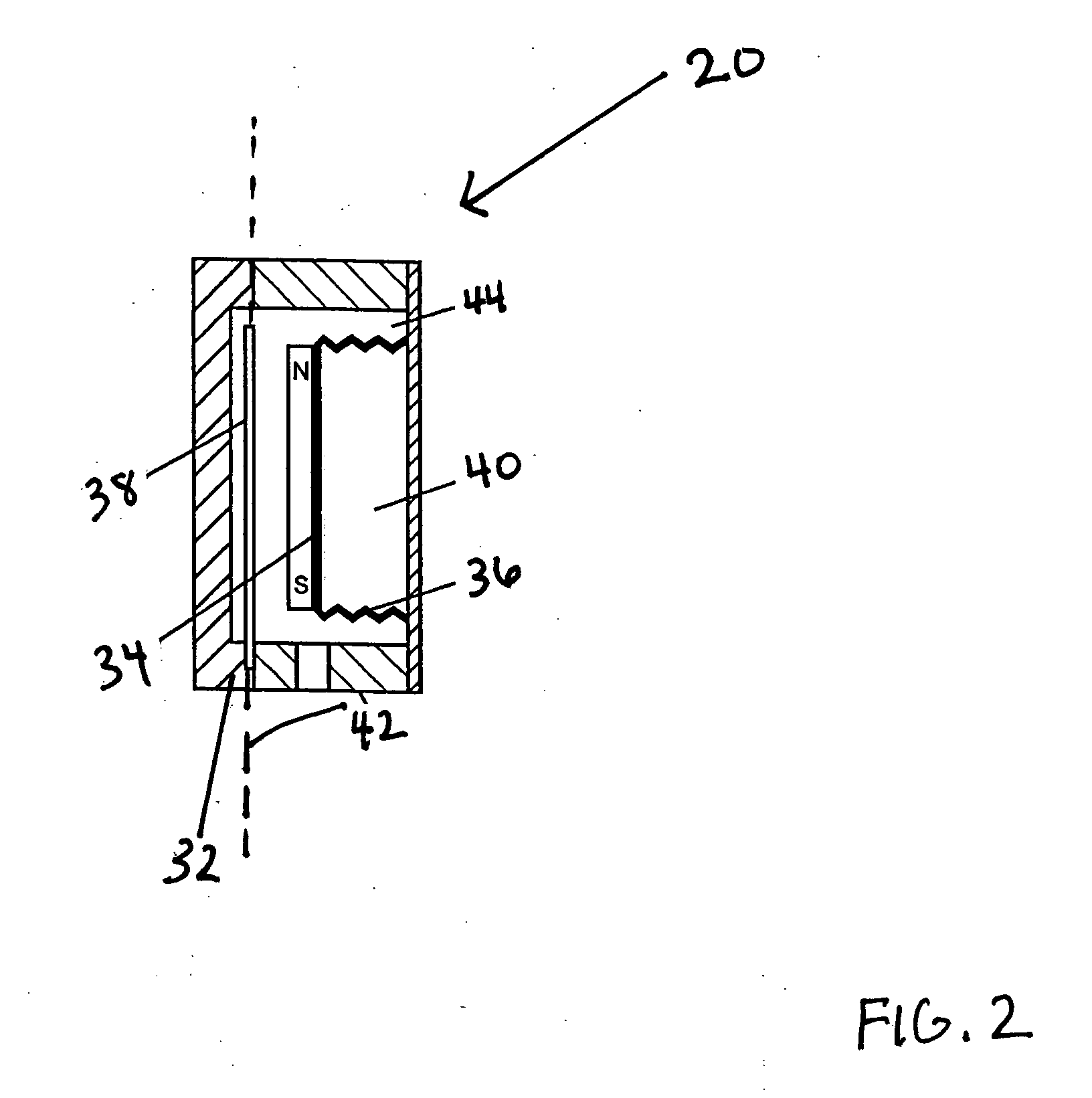
In the magneto-mechanical pressure sensor 20 the magneto-mechanical pressure sensor has a device for modulating the vibration of the magnetostrictive element 38. Preferably, the magneto-mechanical pressure sensor 20 has a pointed clamp or clamping mechanism 70. The pointed clamp mechanism 70 is connected to a location of the magnetostrictive element 38. Preferably, the pointed clamp mechanism 70 is connected to a substantially middle location of the magnetostrictive element 38. The pointed clamp mechanism 70 may be manipulated to move on the magnetostrictive element 38 to change a clamp point on the magnetostrictive element as a function of pressure. In this manner, the pointed clamp mechanism 70 preferably modulates the vibration of the magnetostrictive element 38 and thus changes the resonant frequency detected.

Referring to FIG. 11, there is shown a block diagram for the electromagnetic excitation system 22 for a continuous type magneto-mechanical pressure sensor 20 having the ex...

second embodiment

Referring to FIG. 12, there is shown another or second embodiment of the data interpretation system 26 for a discrete type sensor 20 of the present invention. The oscillator 72 implements a single excitation frequency. The oscillator's output is a current that is amplified by the excitation amplifier 71 to drive the excitation coil 28 and emit the electromagnetic field in the tire 12. In this embodiment, the pickup coil 30 is preferably a sensor receiver coil that picks up the magnetic field due to both the excitation coil 28 and the magneto-mechanical pressure sensor 20 in the tire 12. The data interpretation system 26 has the cancellation circuit 76 that is connected between the pickup amplifier 78 and the excitation coil 28. The cancellation circuit 76 removes any artifact of the excitation coil 28. The cancellation circuit 76, as in the embodiment of FIG. 12, may be a canceling coil (not shown) wrapped in the opposite direction from that of the pickup coil 30, a differencing amp...


PUM


Abstract

An apparatus for monitoring tire pressurization state in a tire has a magneto-mechanical pressure sensor in or on the tire and an electromagnetic excitation system. The electromagnetic excitation system is for interrogating the magneto-mechanical pressure sensor. The apparatus also has a receiver. The receiver is for receiving information from the electromagnetic excitation system. The apparatus also has a data interpretation system for translating the received information into the tire pressurization state. The data interpretation system is connected to a display. The display communicates the tire pressurization state to an operator.

Description

BACKGROUND OF THE INVENTION 1. Field of the Invention The present invention relates to an apparatus that monitors tire pressure. More particularly, the present invention relates to an apparatus that remotely excites a device in a tire, detects data from the device, and processes and displays the data as a tire pressure of the tire to a vehicle operator. 2. Description of the Related Art On board tire pressure sensing devices are known in the art. The tire pressure sensing devices are a convenience to vehicle operators and also a safety feature that has been mandated by the National Highway Traffic Safety Administration (41 CFR Part 571) for reducing the incidence of accidents caused by under-inflated tires. In the final ruling issued by NHTSA, two basic systems for tire pressure monitoring were described. More particularly, direct and indirect pressure measurement devices were described. The indirect tire pressure monitoring systems are found through the rotational speeds as me...

Claims


Application Information

Patent Timeline
IPC IPC(8): B60CB60C23/02B60C23/04G01M15/00
CPCB60C23/0425B60C23/0493B60C23/0428
Inventor HARALAMPU, STEPHEN GEORGEREYNOLDS, CHRISTOPHER HUMEVOGEL, DAVIDZINDLER, JERROLD
Owner HARALAMPU STEPHEN GEORGE
Why Eureka
Try Eureka