Load cell deflasher assembly and method

Inactive Publication Date: 2005-01-06
AUTOMATIC LIQUID PACKAGING SOLUTIONS
View PDF10 Cites 35 Cited by
  • Summary
  • Abstract
  • Description
  • Claims
  • Application Information

AI Technical Summary

Benefits of technology

[0042] The present invention in one aspect advantageously provides for a sensitive monitoring of pressure exerted by a punch upon an extrusion against a die to control, and if necessary abort interrupt and retract, the deflashing punch stroke to the die without deflashing contact. Further, the present invention in another aspect provides for a variable pre-punch positioning of the extrusion in intervening proximity between the punch and the die responsive to prior deflashing pressure measurements to provide an optimum yet adjustable (in view of subsequent environmental factors) deflashing position of the extrusion that minimizes the deflashing pressure exerted by the punch upon the extrusion against the die. Such advantages are desirable to avoid product punch/die rupture and to maintain aseptic protocols despite production run environmental f

Problems solved by technology

Further, such prior art punch and die deflashers deliver the extrusion for deflashing to a set position intervening the punch and die without the ability or structural means for adjusting the deflash position of the extrusion so as to minimize the deflash pressure of the punch against the extrusion at the die.
The lack of more control over the punch stroke and/or the extrusion deflash position in such prior art hydraulic or pneumatic punch actuators may be disadvantageous particularly when used in association with extrusions comprised of c

Method used


Image

  • Load cell deflasher assembly and method
  • Load cell deflasher assembly and method
  • Load cell deflasher assembly and method

Examples


Embodiment Construction

)

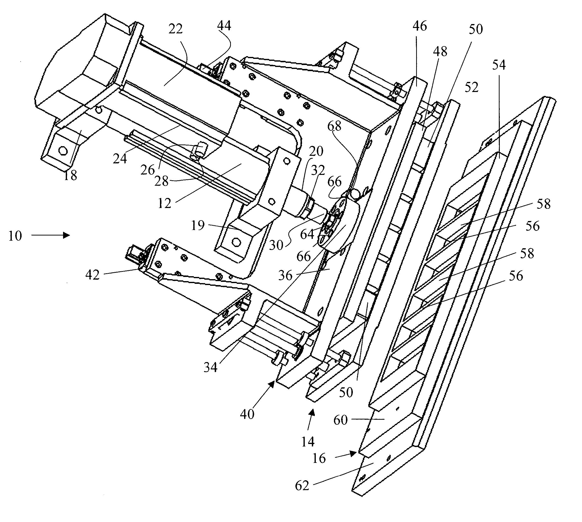
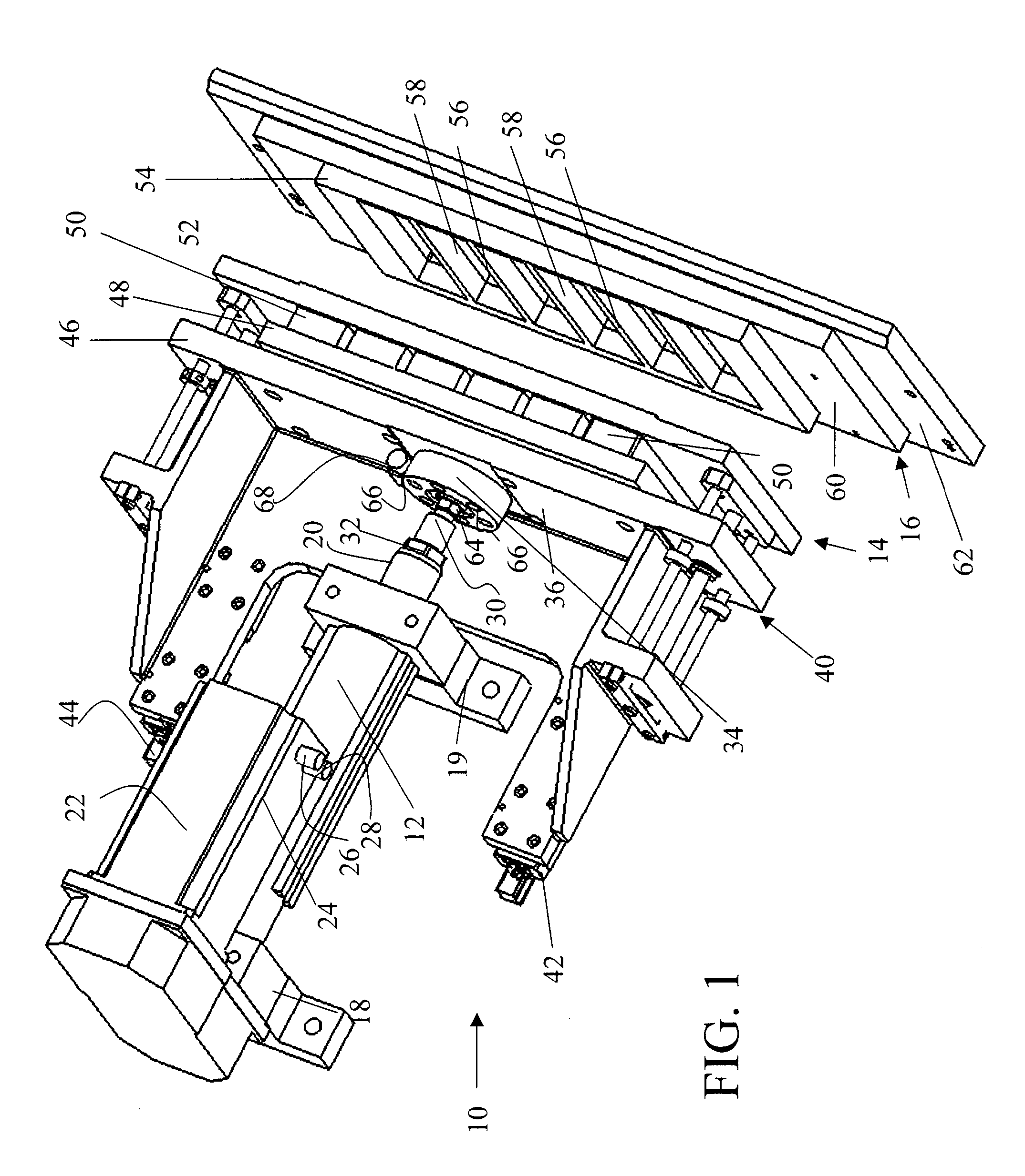
[0059] Referring now to FIG. 1, there is shown a load cell deflasher assembly 10 constructed in accordance with the teachings of the present invention. Load cell deflasher assembly 10 includes a positioning actuator 12 for extension and retraction delivery of a punch 14 to and from a complimentary aligned die 16. The positioning actuator 12 preferably is stabilized within actuator mounting blocks 18, 19 (for clarity, machine surfaces or support plates for the mounting blocks are not illustrated) and includes an extension rod 20 capable of extension and retraction movement in response to a controller, motor, or driver serving as means for powering the positioning actuator 22.

[0060] A servo motor 24 is a preferred controller, motor, or driver for powering the positioning actuator 12 since it operates upon sequential looped counts or pulses. The means for powering the positioning actuator may also comprise an AC motor, a stepper motor, a pneumatic driver, a hydraulic driver, an elect...


PUM

PropertyMeasurementUnit
Pressureaaaaaaaaaa
Surface areaaaaaaaaaaa

Abstract

A load cell deflasher for the punch and die deflash processing of product from an extrusion includes a load cell pressure transducer interconnected with a punch to sense pressure measurements of the punch against the extrusion at the die and communicate the measurements to a programmable logic controller that controls the extension and retraction of the punch to the die and the structure accommodating pre-punch alignment of the extrusion to the die. The pressure measurements are logged in a trending database of the programmable logic controller. If a pressure measurement exceeds a threshold value, to programmable logic controller can command instruct a positioning actuator of the punch to abort its punch stroke prior to completion. If the programmable logic controller determines an upward trend of pressure measurements, an auto-tune mode of the programmable logic controller can command instruct an extrusion card transfer positioning actuator to adjustably position a gripper carriage transferring the extrusion in intervening proximity between the punch and die to an optimal position for extrusion deflashing.

Description

BACKGROUND OF THE INVENTION [0001] 1. Field of the Invention [0002] The present invention relates generally to a punch and die deflasher and method for the processing of product from an extrusion and, more particularly, to a load cell pressure transducer deflasher capable of sensing and communicating pressure measurements to a programmable logic controller that controls the extension and retraction of the punch to the die and / or the structure accommodating pre-punch alignment of the extrusion to the die in response to such pressure measurements. [0003] 2. Description of the Related Art [0004] Heretofore, various punch and die deflashers for the processing of product from an extrusion have been utilized, the same controlling a punch to die stroke by non-reversible and non-sensitive hydraulic or pneumatic stroke actuator controls. In such prior art punch and die deflashers once a punch stroke is initiated, an extension stroke of the punch to the die to deflash product from an extrusio...

Claims


Application Information

Patent Timeline
IPC IPC(8): B26D7/24B26F1/40B29C49/04B29C49/72B29C49/78
CPCB26D7/24B26F1/40B29C49/04Y10S83/914B29C49/78Y10S425/806B29C49/72Y10T83/04Y10T83/178Y10T83/8858
Inventor FARRELL, BRADKREVALD, WALTER R.URASKY, PETER D.
Owner AUTOMATIC LIQUID PACKAGING SOLUTIONS
Why Eureka
Try Eureka