Antenna device and communication device using antenna device

a communication device and antenna technology, applied in the field of reading/writing antenna apparatus, can solve the problems of not meeting the needs of not meeting the requirements peculiar to small portable electronic devices, and conventional techniques cannot implement compact and thin loop antennas optimum for readers/writers, etc., to achieve effective utilization, increase the range of communication, and improve the effect of performan

Inactive Publication Date: 2005-01-06
SONY CORP
View PDF4 Cites 103 Cited by
  • Summary
  • Abstract
  • Description
  • Claims
  • Application Information

AI Technical Summary

Benefits of technology

[0021] The present invention has another object to provide an antenna apparatus capable of expanding the range of communications between an IC card and reader / writer by controlling, and effectively utilizing, the distribution of a radiated electromagnetic field, and a communication apparatus using the antenna apparatus.
[0022] The present invention has still another object to provide an antenna apparatus for a reader / writer, formed to be smaller and have a higher performance by reducing the influence of the material of a housing for the antenna apparatus, and a communication apparatus using the antenna apparatus.

Problems solved by technology

Different from the stationary electronic devices, the small portable-type electronic device is limited in size to assure its portability.
Therefore, any well worked-out disposition of the loop coil in a space inside the housing will not effectively solve the problems in assuring a space for the loop coil installed inside the housing, that is enough to inhibit the electromagnetic field radiated from the loop antenna 102 from adversely affecting the electronic circuit board and the like disposed near the inner wall of the housing as well as to prevent the metallic housing from affecting the loop antenna 102.
Further, because of the limited location of installation and geometric relation of the reader / writer 101 with location of any other functional part such as a keyboard or the like, a desired position of transmission and reception of the reader / writer 101 cannot always be at the center of the loop antenna 102, which will not meet a demand peculiar to the small portable-type electronic device, such as a requirement for a freedom of setting the transmission / reception position to attain an easier operability of the electronic device itself.
Any of the aforementioned conventional techniques cannot implement any compact and thin loop antenna optimum for a reader / writer in a small portable-type electronic device material- and space-limited in power consumption and location of installation of the loop antenna.

Method used


Image

  • Antenna device and communication device using antenna device
  • Antenna device and communication device using antenna device
  • Antenna device and communication device using antenna device

Examples


Embodiment Construction

[0075] The present invention will be described in detail concerning the antenna apparatus and the communication apparatus using the antenna apparatus as the embodiments thereof with reference to the accompanying drawings.

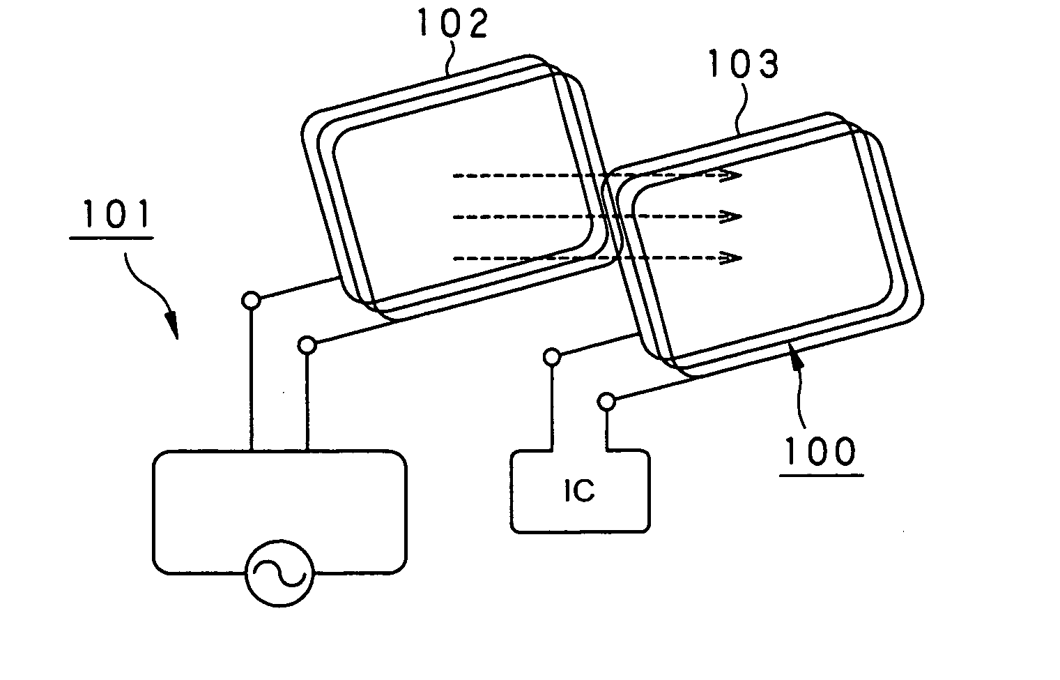
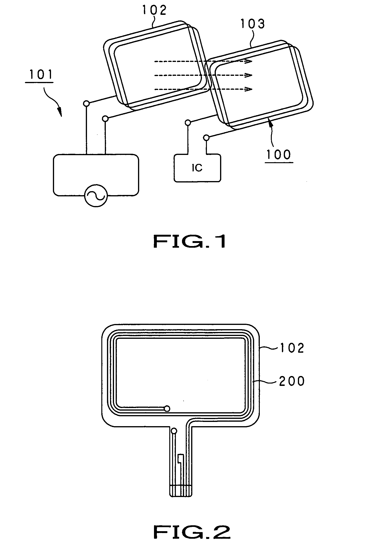
[0076] As shown in FIG. 7, the RFID system according to the present invention is composed of a contactless IC card 1, and a reader / writer (will be referred to as “R / W” hereunder) 50 to write and read data to and from the IC card 1.

[0077] The IC card 1 is of a battery-less type compliant with ISO 7810, for example. Namely, it has no power source such as a battery or cell. The IC card 1 is formed rectangular to have the same size as the so-called credit card, namely, it is palm-sized. The IC card 1 has provided on a circuit board built therein a loop antenna 2 that couples with an electromagnetic field to send and receive data, and an IC (integrated circuit) 3 having integrated therein electronic circuits that make various operations for writing and reading data.

[0...


PUM


Abstract

An antenna apparatus (60) is provided which is used in a recorder and / or player to write and read data to and from a contactless IC card (1). The antenna apparatus (60) includes a loop coil (61) to radiate an electromagnetic field for magnetic coupling with a loop coil (4) at the IC card (1) to send and receive data to and from the IC card (1), and a magnetic sheet (62) disposed to face the main side of the loop coil (61), opposite to the main side facing the IC card (1). The magnetic sheet (62) has the specific permeability μ′ and product Ms.t of saturation magnetization Ms and thickness t thereof set in accordance with a necessary range of communications with the contactless IC card (1).

Description

TECHNICAL FIELD [0001] The present invention relates to a reader / writer antenna apparatus for writing and reading data to and from a contactless IC (integrated circuit) card adopting the technique of electromagnetic-inductive coupling and a communication apparatus using the antenna apparatus. [0002] This application claims the priority of the Japanese Patent Application No. 2002-284177 filed on Sep. 27, 2002 and No. 2003-3739 filed on Jan. 9, 2003, the entirety of which is incorporated by reference herein. BACKGROUND ART [0003] Recently, a so-called RFID (radio frequency identification) system using a contactless IC card, IC tag or the like has been introduced into the fields of art such as an automatic ticket checker used in the railway station, security system for checking people going to enter or exit from a building, electronic money system, etc. As schematically illustrated in FIG. 1, the RFID system includes a contactless IC card 100 and a reader / writer 101 to write and read d...

Claims


Application Information

Patent Timeline
Patent Type & Authority Applications(United States)
IPC IPC(8): G06K7/00G06K17/00G06K7/08G06K7/10G06K19/077H01Q1/22H01Q1/38H01Q7/00H01Q7/04H01Q7/06
CPCG06K7/0008G06K7/10316G06K7/10336G06K7/10346G06K7/10386G06K19/07749H01Q7/06G06K19/07779H01Q1/22H01Q1/2216H01Q1/38H01Q7/04G06K19/07771
Inventor AKIHO, HIRAKUOKAZAKI, YUTAKAGOTO, KAZUOKIKUCHI, AKIHIRO
Owner SONY CORP
Why Eureka
Try Eureka