Nail gun provided with duster function

a nail gun and function technology, applied in the field of nail guns, can solve the problems of uncontrollable movement around the user, high duster pressure, air raising dust around the user,

Inactive Publication Date: 2005-01-06
HITACHI KOKI CO LTD
View PDF20 Cites 5 Cited by
  • Summary
  • Abstract
  • Description
  • Claims
  • Application Information

AI Technical Summary

Benefits of technology

[0006] It is an object of the present invention to overcome the above-described problems and to provide an improved nail gun having a dust

Problems solved by technology

Because the nail driving pressure cannot be lowered, the duster pressure is undesirably high.
When the excessively high pressure is ejected from the nozzle 624, the

Method used


Image

  • Nail gun provided with duster function
  • Nail gun provided with duster function
  • Nail gun provided with duster function

Examples


first embodiment

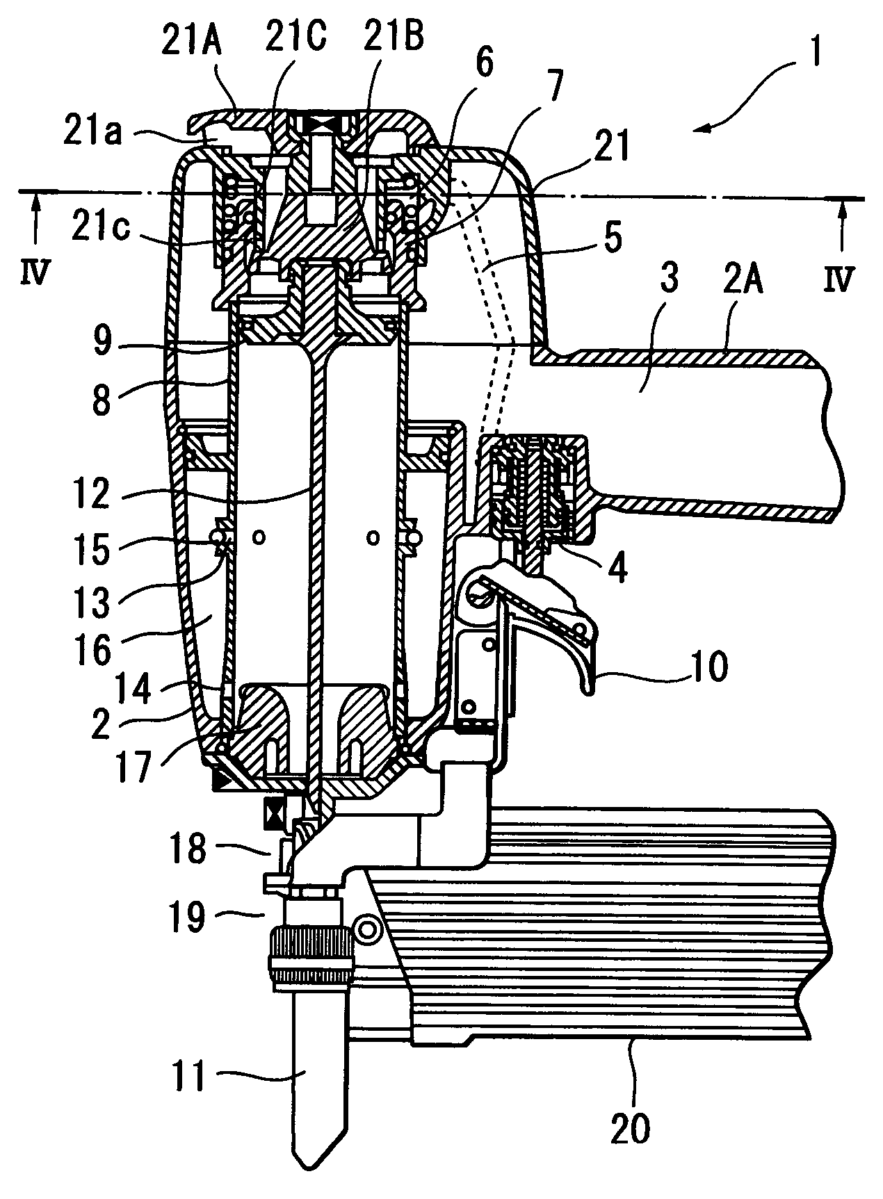
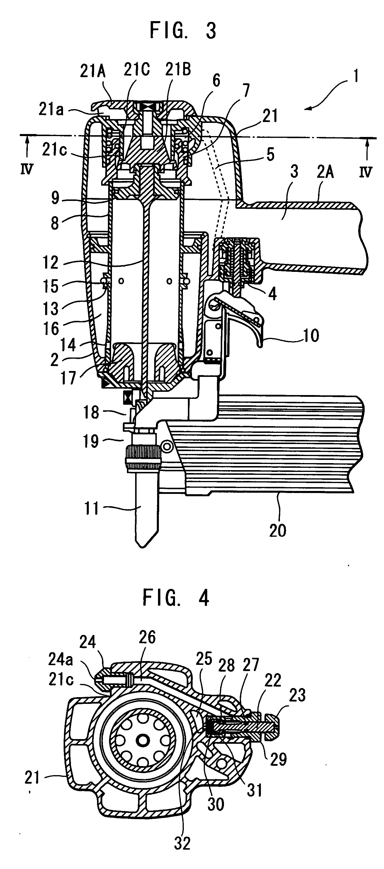
[0023] A nail gun according to the present invention will be described with reference to FIGS. 3 through 6. The nail gun 1 includes a main housing 2, a handle 2A integrally therewith, and an exhaust cover 21 fixed to an upper end of the main housing 2 by bolts. A combination of the main housing 2, the handle 2A and the exhaust cover 21 serves as a main body and defines therein a compressed air chamber 3. An air hose (not shown) is connectable to the handle 2A. The air hose is fluidly connected to a compressor (not shown) so as to supply compressed air into a compressed air chamber 3.

[0024] A cylinder 8 is disposed in and fixed to the main housing 2. The cylinder 8 is formed with intermediate vent holes 13 at an axially intermediate position thereof and with lower vent holes 14 at a lower end portion thereof, A return air chamber 16 is defined by an inner peripheral surface of the main housing 2 and an outer peripheral surface of the cylinder 8 for accumulating therein compressed air...

fourth embodiment

[0050]FIG. 9 shows an essential portion of a pressure reducing arrangement in a nail gun according to the present invention. In this embodiment, an exhaust cover 321 provides a second air passage 326 whose internal volume is greater than that of the foregoing embodiments. Therefore, greater air expansion can be provided in the second air passage 326 to accelerate reduction of air pressure in the second air passage 326 after throttling at the throttle 32.

[0051] A pressure reducing arrangement of a nail gun according to a fifth embodiment of the present invention will be described with reference to FIGS. 10 and 11. In the fifth embodiment, instead of the formation of the throttle 32, 132, 232 or in addition to these throttles, a pressure regulation valve mechanism 33 is provided for providing a compressed air to the duster nozzle 24 at a pressure level lower than that of the compressed air chamber 3.

[0052] An exhaust cover 421 is formed with a third air passage 34 for providing fluid...


PUM


Abstract

A pneumatically powered nail gun having a duster mechanism which is also pneumatically powered with the same pneumatic source. The nail gun includes a main body having a lower end and defines therein a compressed air chamber. A cylinder piston arrangement is disposed in the main body, and the compressed air is selectively applied to the piston for moving a driver blade connected to the piston to drive a nail. The duster mechanism includes a duster nozzle provided at the main body for ejecting a compressed air therethrough. A pressure release valve is disposed at an air passage extending between the duster nozzle and the compressed air chamber for selectively shutting off a fluid communication therebetween. A pressure regulating section is disposed at the air passage for providing a compressed air passing through the duster nozzle at a pressure lower than that in the compressed air chamber.

Description

BACKGROUND OF THE INVENTION [0001] The present invention relates to a nail gun provided with an air duster which ejects compressed air for removing dust, wood chips and wood shavings out of an intended nail driving area. [0002] Laid open Japanese Patent Application publication No.Hei 10-109280 discloses, as shown in FIGS. 1 and 2, a nail gun 601 having nail driving function A and duster function B. The nail gun 601 includes a main housing 602 and a handle 602A. In the main housing 602 a compressed air chamber 603 is provided, and a cylinder, a piston and a driver blade are disposed. The piston is reciprocally movable in the cylinder by pneumatic pressure applied in the compressed air chamber 603 through a hose 602B, and the driver blade extends from the piston for driving a head of a nail. A safety arm 611 is axially movably provided at a lower portion of the main housing 602. The safety arm 611 has a tip end abuttable on a workpiece. A magazine 620 is also provided at the lower por...

Claims


Application Information

Patent Timeline
IPC IPC(8): B25C1/04
CPCB25C1/047
Inventor ISHIZAWA, YOSHINORINAKANO, YOSHIHIRO
Owner HITACHI KOKI CO LTD
Why Eureka
Try Eureka