Anchor ring

Inactive Publication Date: 2005-01-06
STRAUB WERKE
View PDF3 Cites 21 Cited by
  • Summary
  • Abstract
  • Description
  • Claims
  • Application Information

AI Technical Summary

Benefits of technology

On clamping of the pipe coupling, the clamping ring is reduced in circumference and hence its internal diameter is reduced. The teeth slide over the circumference of the pipe surface. In order to permit this movement, it is advantageous if the la

Problems solved by technology

Particularly in the case of such pipes of titanium alloys or chromium nickel steels, engagement of the clamping rings known to date is problematic in some cases.
Particularly for extreme materials, i.e.

Method used


Image

  • Anchor ring
  • Anchor ring
  • Anchor ring

Examples


Embodiment Construction

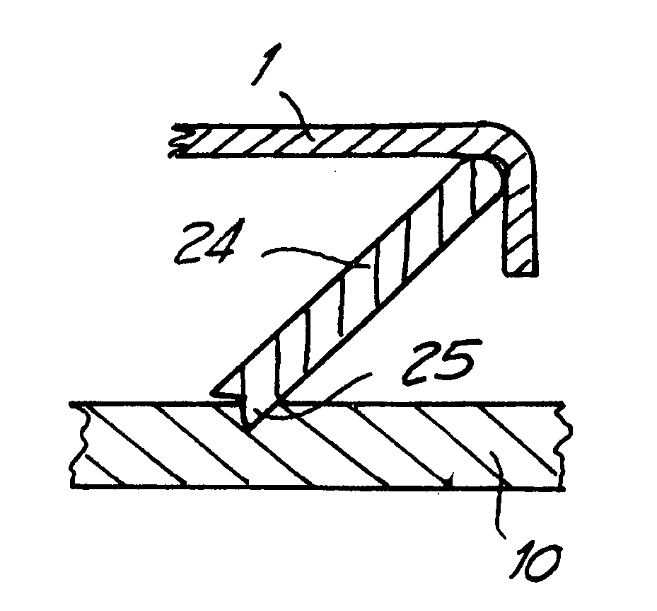
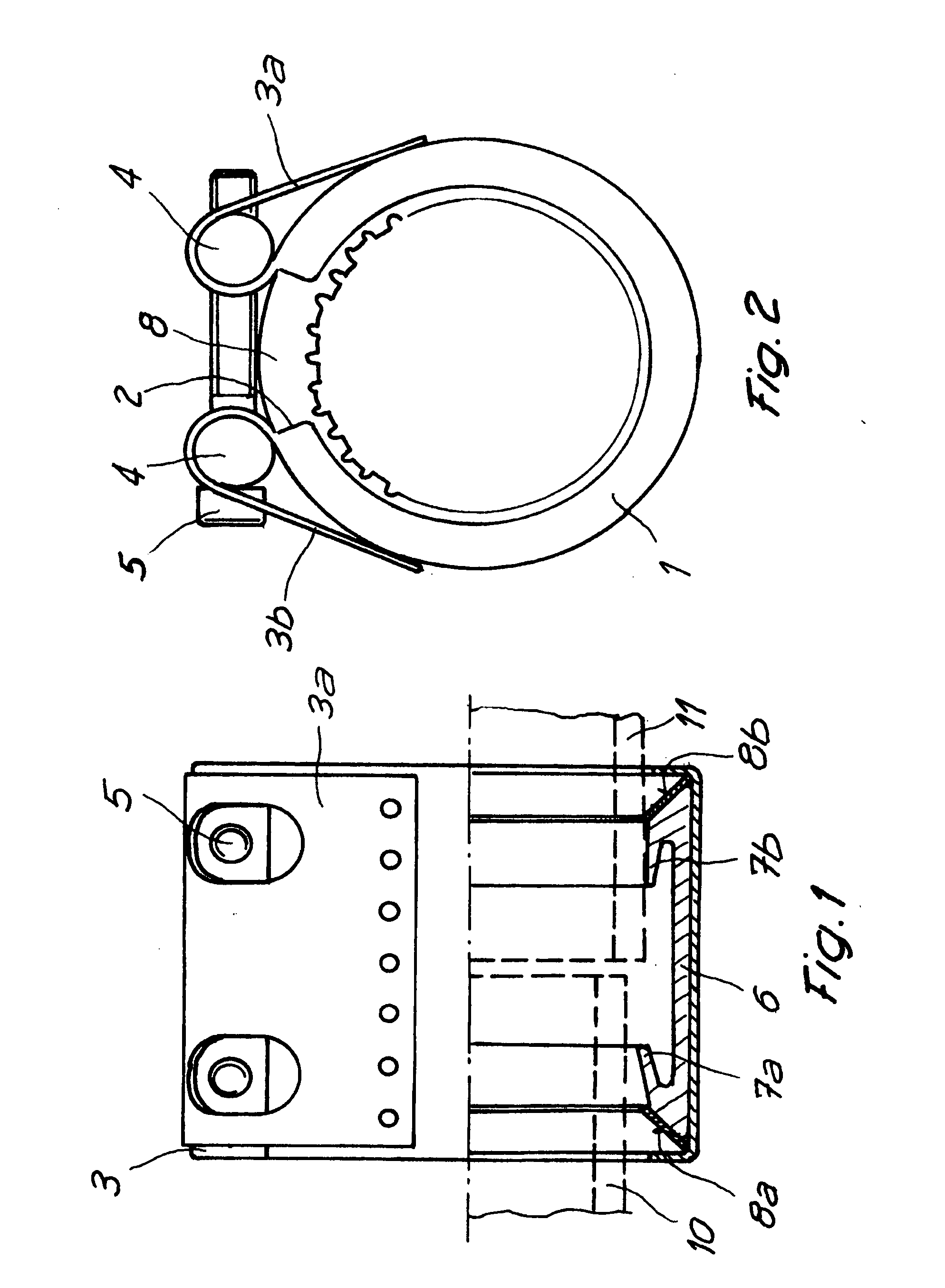
The pipe coupling shown in FIGS. 1 and 2 has a substantially cylindrical housing 1 provided with a longitudinal slot 2, the free ends of the housing 1 being in the form of bent-over straps 3a, 3b. Cylindrical locking pins 4 are arranged in the straps 3a, 3b. The housing 1 can be radially clamped by means of locking bolts 5 which pass through the locking pins 4, it being possible for the longitudinal slot 2 to become narrower. A sealing sleeve 6 preferably consisting of an elastomer and intended for sealing the pipes to be connected is arranged in the housing 1. The sealing sleeve 6 has elastically deformable sealing lips 7a, 7b for this purpose. Present at both ends of the sealing sleeve 6 are clamping rings 8, which are preferably installed at about 45° to the longitudinal axis of the pipe coupling and are supported on the housing 1 in the corner of the side walls of the housing 1 which are directed radially inwards.

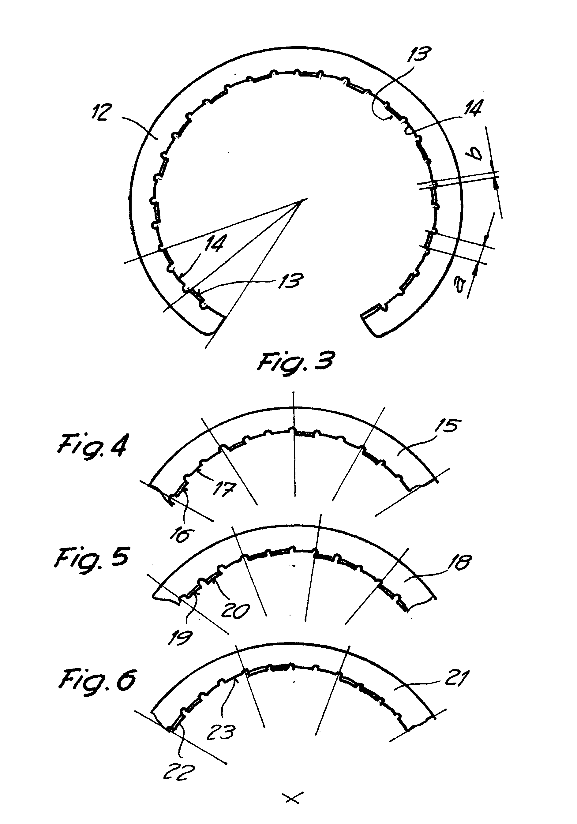
As shown in particular in FIG. 2, the clamping rings 8 are prov...


PUM

PropertyMeasurementUnit
Circumferenceaaaaaaaaaa

Abstract

A clamping ring for pipe couplings, in particular for the axial tension-proof connection of smooth-ended pipes is supported on a housing and on the pipe to be connected, where the clamping ring has teeth which can be caused to engage the pipe, the total number of teeth being divided into repeating groups of teeth, at least one group having at least two teeth differing from one another.

Description

BACKGROUND The invention relates to a clamping ring for pipe couplings, in particular for the axially tension-proof connection of smooth-ended, metallic pipes, the pipe couplings having a housing which can be clamped around the pipes to be connected and having at least one sealing element preferably consisting of an elastomer and, in the clamped state of the pipe coupling, at least one clamping ring being supported axially and / or radially on the one hand on the housing and on the other hand on one pipe end, the clamping ring having on its inside teeth which can be made to engage the pipe. The penetration of the teeth into the pipe wall results in an interlocking connection which permits secure clamping of the pipes to be connected in the pipe coupling. In the pipes used today in pipeline construction, different pipe materials and pipe wall thicknesses are used depending on the application. For example, in lightweight construction for aircraft or other vehicles, aluminium alloys an...

Claims


Application Information

Patent Timeline
IPC IPC(8): F16L17/04
CPCF16L17/04F16L47/12F16L21/08F16L21/005
Inventor SCHERRER, ANTON
Owner STRAUB WERKE
Why Eureka
Try Eureka