

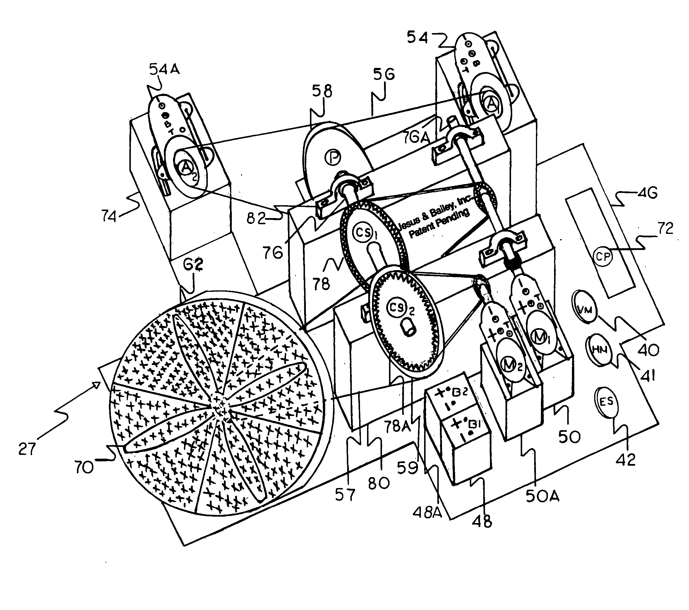
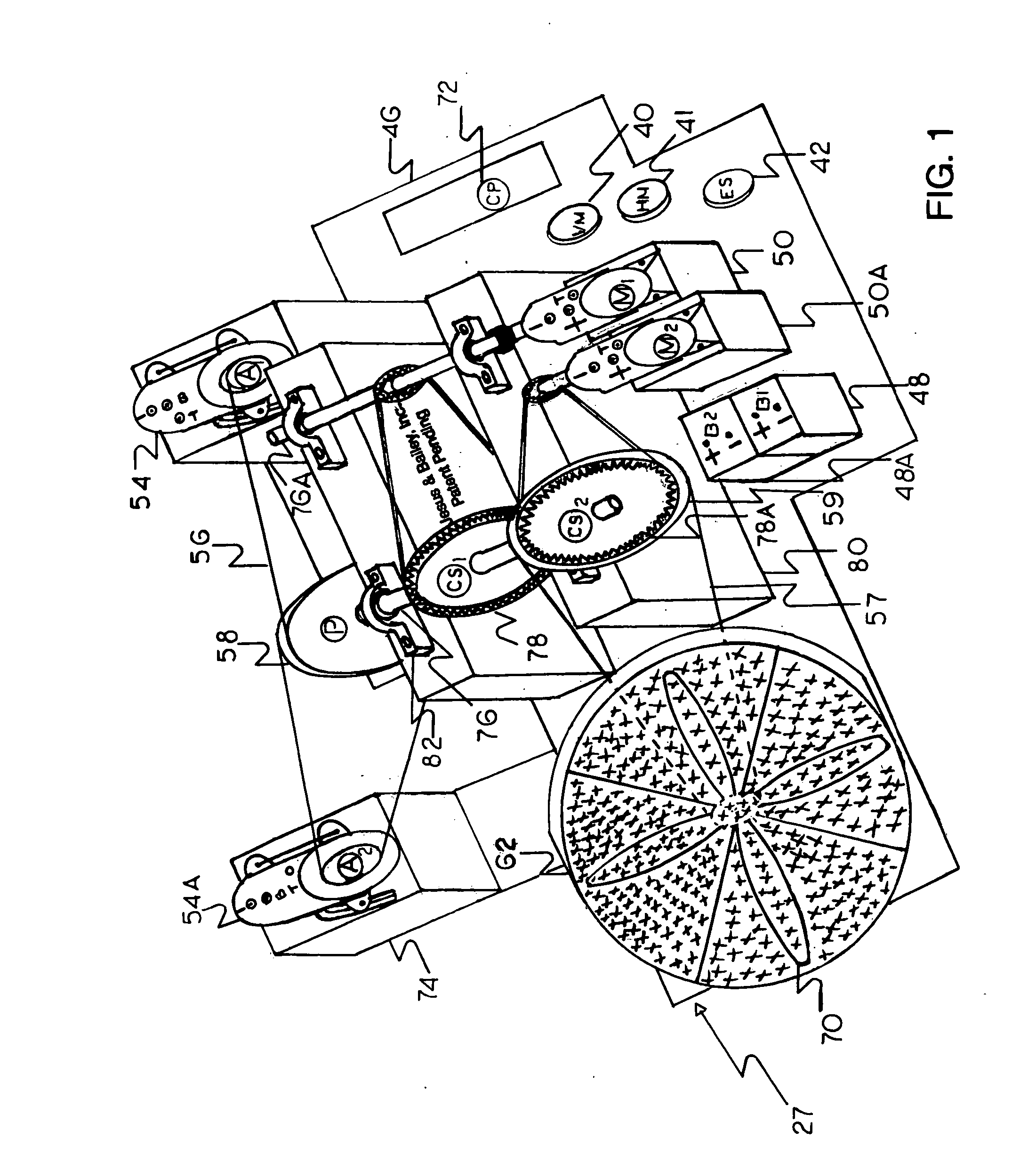
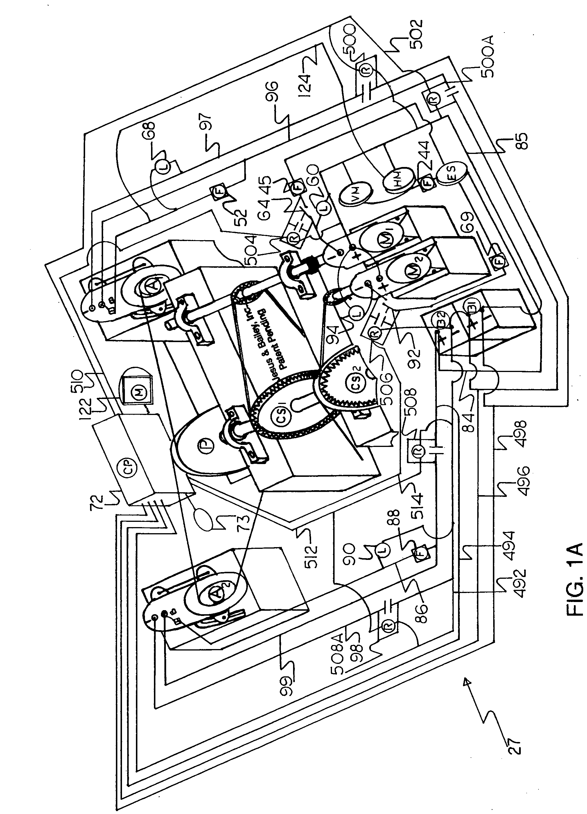
Perpetual motion fan module
a technology of permanent motion and fan module, which is applied in the direction of dynamo-electric brake control, dynamo-electric machines, control systems, etc., can solve the problems of inability to work, failure of the system, and limited mobility of users, so as to reduce friction, reduce friction, and produce more electrical energy
- Summary
- Abstract
- Description
- Claims
- Application Information
AI Technical Summary
Benefits of technology
Problems solved by technology
Method used
Image

Examples
Embodiment Construction
may be better understood, and that the present contribution to the art can be more fully appreciated, additional features of the invention will be described hereinafter. It should be appreciated by those skilled in the art that the conception and the disclosed specific methods, and structures, may be readily utilized as a basis for modifying or designing other structures, for carrying out the same purposes of the present invention. It should be realized by those skilled in the art, that such equivalent methods and structures do not depart from the spirit and scope of the invention.
[0013] In this respect, before explaining at least one embodiment of the invention in detail, it is to be understood that the invention is not limited to the details of construction, and to the arrangements, of the components, as set forth in the following description, or illustrated in the drawings. The invention is capable of other embodiments, and of being practiced and carried out in various ways. Also...
PUM
 Abstract
Description
Claims
Application Information