Wireless-based system and method for hull-based sensing

a sensor and wireless technology, applied in the field of shipboard sensing, can solve the problems of limited capability to measure and analyze the complexity in-situ, and achieve the effect of high sensor coun

Inactive Publication Date: 2005-01-06
HOUSTON BRIAN H +1
View PDF7 Cites 5 Cited by
  • Summary
  • Abstract
  • Description
  • Claims
  • Application Information

AI Technical Summary

Problems solved by technology

Naval tacticians and oceanographers appreciate the complexity of the ocean environment, but have had limited capability to measure and analyze its complexity in-situ.
Onboard naval ships, submarines, and aircraft (i.e., naval platforms) this limited capability has been particularly true.
The above-identified systems having hull-based sensors are limited, however, in performance and by cost due to a requirement to employ the use of conventionally wired and / or optical buss structures for the communication of data.
Further, the development and deployment of distributed monitoring and control of the sensors has been hindered in the past by the requirements of complex installation and communication network requirements.
Conventional distributed sensors require cable interface, and consequently required extensive modification to structures for sensor installation.

Method used


Image

  • Wireless-based system and method for hull-based sensing
  • Wireless-based system and method for hull-based sensing
  • Wireless-based system and method for hull-based sensing

Examples


Embodiment Construction

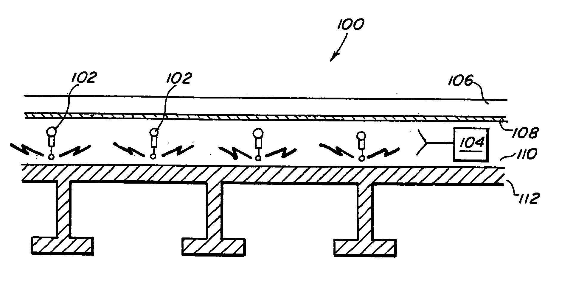
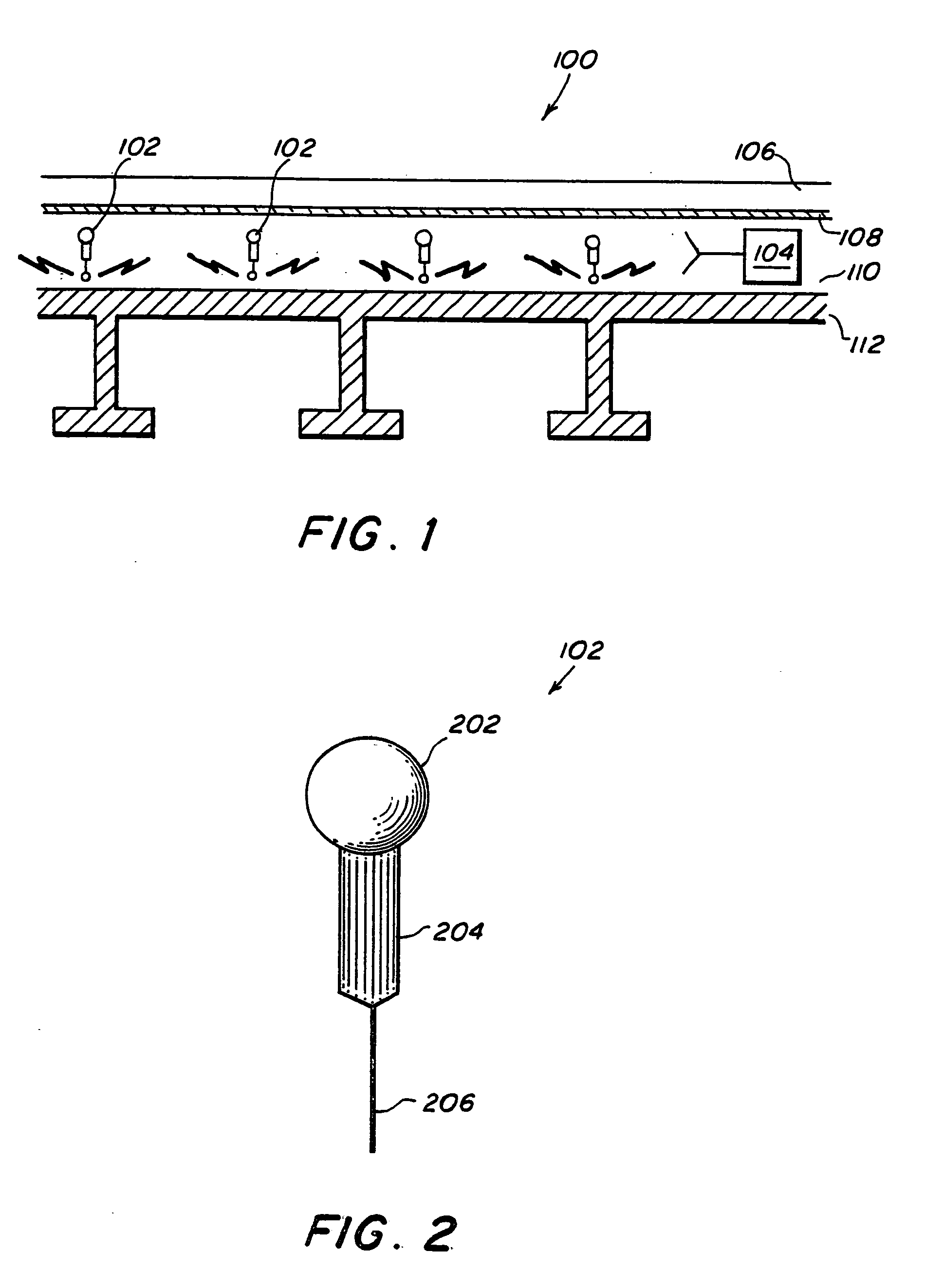
DEFINITION(S): As used herein, when reference is made to a sensor(s) as being disposed within a waveguide or electromagnetic waveguide, this includes the positioning of just some portion of the sensor in the waveguide, e.g. the antenna, while another portion of the sensor, e.g. the body, may be disposed outside the waveguide, as when the antenna is projecting into the waveguide with the base or body portion of the sensor not disposed therein.

In the drawings, like or similar elements are designated with identical reference numerals through the drawings, and the various elements depicted are not necessarily drawntoscale.

Referring now to FIG. 1, there is shown a schematic of a planar waveguide 100 formed on the outer surface of a hull of a vessel in an exemplary embodiment of the present invention. The waveguide 100 comprises an outer dielectric layer 106, an optional (as discussed further below) metal coat layer 108, an inner dielectric layer 110, and the outer surface 112 of a hul...


PUM


Abstract

The present invention describes a wireless system and method for distributing sensors in large numbers that makes possible the application of a number of algorithms for the extraction of important physical quantities. More specifically, the method involves (a) formation of an electromagnetic waveguide by the application of a polymer, or other dielectric material, on the exterior of the hull of a vessel; (b) insertion of sensors / radio units within the waveguide, the sensors being arranged to sample the fields of interest; and (c) insertion of radio transceiver base stations in the waveguide to communicate and extract data from the sensor / radio units. The wireless system of the present invention is implemented with a very high sensor count whose outputs are processed to recover exterior field quantities without the requirement of direct measurements off of the vessel's structure.

Description

BACKGROUND OF THE INVENTION 1. Field of the Invention This invention relates to shipboard sensing, and more particularly, to an apparatus and method for making spatially dense measurements of physical quantities. 2. Description of Related Art The current state-of-the-art includes a large number of commercial and defense applications of hull-based sensors. These include, for example, arrays of sensors attached to the exterior of submarines, surface ships, towed underwater vehicles, Autonomous Underwater vehicles (AUV), and Underwater Unmanned Vehicles (UUV). Naval tacticians and oceanographers appreciate the complexity of the ocean environment, but have had limited capability to measure and analyze its complexity in-situ. Onboard naval ships, submarines, and aircraft (i.e., naval platforms) this limited capability has been particularly true. Most acoustic propagation predictions and dependent tactical algorithms use as inputs averaged historical and infrequently collected in-sit...

Claims


Application Information

Patent Timeline
Patent Type & Authority Applications(United States)
IPC IPC(8): B63B9/00
CPCB63B9/001B63B71/00
Inventor HOUSTON, BRIAN H.MAIN, GEOFFREY L.
Owner HOUSTON BRIAN H
Why Eureka
Try Eureka