Color image formation apparatus

a color image and apparatus technology, applied in the field of image formation apparatus improvement, can solve the problems of difficult to ensure the positioning accuracy of each image formation unit, easy instability of the tip state of paper, and inability to ensure the transferability of transfer materials, etc., and achieve the effect of enhancing the reliability of image quality

Inactive Publication Date: 2005-01-06
PANASONIC CORP
View PDF8 Cites 2 Cited by
  • Summary
  • Abstract
  • Description
  • Claims
  • Application Information

AI Technical Summary

Benefits of technology

[0011] It is therefore a first object of the invention to provide an image formation apparatus for enabling components to be well positioned in an apparatus main unit.
[0012] It is a second object of the invention to provide an image formation apparatus for making it possible to suppress a color shift and color unevenness of a color image accompanying transport unevenness of a transfer material and miniaturize the apparatus itself.

Problems solved by technology

Thus, it is difficult to ensure the positioning accuracy of each image formation unit in the apparatus main unit.
As for the conventional image formation apparatus of the portrait orientation type, each image formation unit can be attached and detached from the direction orthogonal to the transfer material transport passage of roughly vertical portion, so that each image formation unit can be positioned in the apparatus main unit by a unit positioning section formed on both sides of a cabinet and it becomes easy to ensure the positioning accuracy; in contrast, however, a disadvantage occurs in the transfer material transportability.
In the transfer roll transport technique, if the image formation unit spacing is wide to some extent, paper passes through the transfer part of one image formation unit, the pass-through paper portion becomes long, the tip state of the paper becomes easily unstable in such a manner that the tip of the paper curls or remains straight, and the tip position of the paper arriving at the transfer part of the next image formation unit easily varies.
Thus, the write start position of each color component toner image relative to the paper at the transfer part of each image formation unit shifts, causing a color shift or color unevenness phenomenon of a color image.
However, as the image formation unit spacing is wider, a walk phenomenon in which when the paper transport belt moves, it meanders in the width direction increases, and color shift or color unevenness of color image worsens in the orthogonal direction (width direction) to the paper transport direction.

Method used


Image

  • Color image formation apparatus
  • Color image formation apparatus
  • Color image formation apparatus

Examples


embodiment 1

[0078] Referring now to the accompanying drawings, a first embodiment of the invention will be discussed.

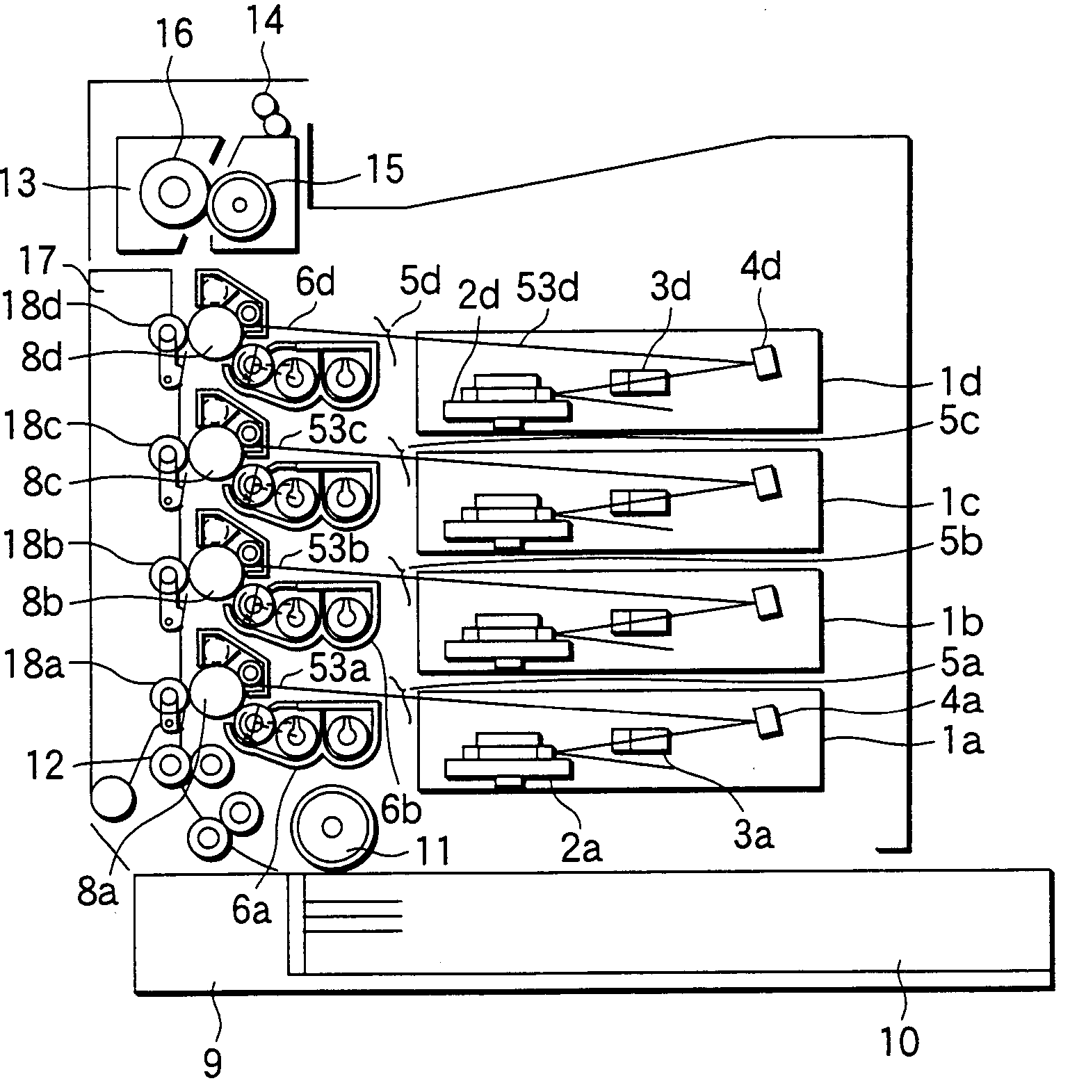
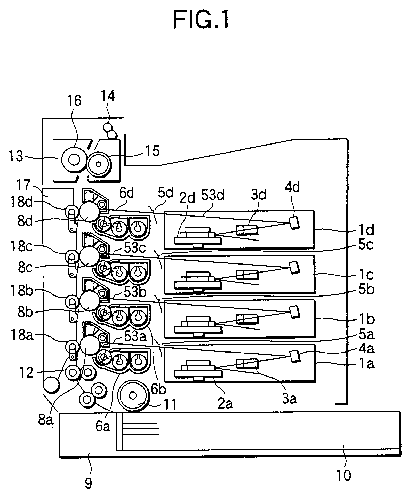
[0079]FIG. 1 shows an embodiment of a color image formation apparatus incorporating the invention. In the Figure, the color image formation apparatus includes image formation units (5a to 5d) of four colors (in the embodiment, yellow, magenta, cyan, and black) arranged in a longitudinal direction, a paper feed cassette 9 disposed below the image formation units for storing supplied paper 10, and a paper transport passage as a transport passage of paper 10 from the paper feed cassette 9, placed in a vertical direction at positions corresponding to the image formation units (5a to 5d).

[0080] In the embodiment, the image formation units (5a to 5d) and reflecting mirrors (4a to 4d) usually form yellow, magenta, cyan, and black toner images in order from the upstream side of the paper transport passage. The image formation apparatus includes the image formation units (5a to 5d) for ...

embodiment 2

[0123] A second embodiment of an image formation apparatus incorporating the invention will be discussed with reference to FIGS. 8 and 9.

[0124] Components in the second embodiment similar to those in the first embodiment will not be discussed again in detail. In FIG. 8, a plurality of photoconductor units 8 (8a to 8d) are fixed to and supported on a cabinet 48 using metal sheets each shaped roughly like angular U in combination with screws, etc. A center shaft 28a of a photoconductor 34a positioned upstream in the paper transport direction is used as the positioning reference of an integral photoconductor unit group 50 and a center shaft 28d of a photoconductor 34d positioned downstream is fitted into an abutment part 54 (described later), whereby it is made to function as a whirl stop pin (shaft).

[0125] The shapes of a unit guide and positioning member, a developing unit, and a transfer member in a main unit housing are similar to those of the first embodiment except for the port...

embodiment 3

[0128]FIG. 10 shows a third embodiment of a color image formation apparatus incorporating the invention. In the Figure, the color image formation apparatus includes image formation units (102a to 102d) of four colors (in the embodiment, yellow, magenta, cyan, and black) arranged in a longitudinal direction, a paper feed cassette 127 disposed below the image formation units for storing supplied paper 103, and a paper transport passage 134 as a transport passage of paper from the paper feed cassette 127, placed in a vertical direction at positions corresponding to the image formation units (102a to 102d).

[0129] In the embodiment, an optical unit 140 includes an incidence optical unit (not shown) having a cabinet for holding color semiconductor lasers integrally and optical elements forgiving a different angle to each color laser beam and making the color laser beam incident on a single polygon mirror surface rotating at high speed, a single image-forming lens 112 having Fθ characteri...


PUM


Abstract

In an image formation apparatus having a photoconductor unit including a photoconductor and a developing unit for storing toner supplied to the photoconductor, the developing unit is displaceably placed in an apparatus main unit, and then, the photoconductor unit is detachably placed in the apparatus main unit and is positioned at a predetermined position, thereby the displaceable developing unit previously placed is positioned relative to the photoconductor unit.

Description

BACKGROUND OF THE INVENTION [0001] This invention relates to improvement in an image formation apparatus, such as an electrophotographic printer or copier, particularly including a plurality of image formation units disposed along a transfer material transport passage for successively transferring toner images to a transfer material moving on the transfer material transport passage. [0002] Known as a conventional image formation apparatus is an apparatus called tandem type including a plurality of image formation units disposed on a transfer material transport passage extending in a horizontal direction, for example, for successively transferring toner images from the image formation units to a transfer material moving along the transfer material transport passage and forming a color image on the transfer material. [0003] The image formation unit refers to a pair of a photoconductor unit having a photoconductor on which an electrostatic latent image is formed and a developing unit f...

Claims


Application Information

Patent Timeline
Patent Type & Authority Applications(United States)
IPC IPC(8): G03G15/01G03G15/04G03G15/08G03G21/16G03G21/18
CPCG03G15/04G03G21/1821G03G21/1839G03G21/1857G03G15/0855G03G15/0435G03G15/0887G03G15/0194G03G15/0865G03G21/1604
Inventor TANIZAKI, JUNICHISHIMOKAWA, TAKUOKITAOKA, YOSHITAKA
Owner PANASONIC CORP
Why Eureka
Try Eureka